Top Case Assemblies
4
-
46
Removal and Replacement
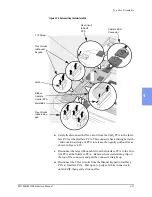
b.
Remove the 4 Torx #10 screws now visible around the edge of the
keypad. See Figure 4-27.
c.
Remove the Manual Door shaft and rails. Note the orientation of the
shaft between the rails. If at all possible keep the shaft captured
between the rails.
d.
Using a sharp tool such as a utility knife, carefully pick up one corner
of the membrane switches and peel the entire switch assembly off the
case. Be careful not to gouge the case. The membrane switches will
likely peel apart into several layers - be sure to remove all layers.
e.
Slide the 2 flex circuit tails out of the slot in the case.
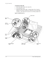
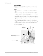
7. Turn the top case over and loosen the Interface PCA (do not remove it) as
follows:
a.
Remove (1) T10 screw from the Interface PCA (near the ECG and
SpO
2
connections). See Figure 4-26 on page 4-44.
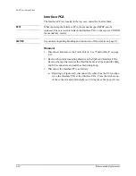
b.
Release the retaining clip at the end of the PCA nearest the Ambient
Light Sensor. Use a small flat bladed screwdriver to gently pry
between the clip and the PCA, levering the PCA up and free of the
retaining clip. Simply leave the PCA loose in position.
Summary of Contents for Heartstart XLT
Page 1: ...H E A R T S TA R T X LT S e r v i c e M a n u a l M 3 5 0 0 B M 5 5 0 0 B ...
Page 2: ......
Page 3: ...Service Manual M3500B HeartStart XLT M5500B Heartstart 4000 Defibrillator Monitor ...
Page 6: ......
Page 16: ......
Page 20: ......
Page 52: ......
Page 216: ......
Page 223: ......
Page 224: ...M3500 90900 Printed in USA February 2003 Second Edition M3500 90900 2 ...

