Top Case Assemblies
4
-
48
Removal and Replacement
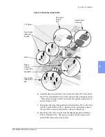
3. Replace and reconnect the Interface PCA as follows:
a.
Replace the Interface PCA into position, snapping it under the
retainer clip and replacing its screw. Visually check the connections
to the PCA to be sure none have loosened and that all are properly
aligned. See Figure 4-29 on page 4-51.
b.
Replace (1) T10 screw in the Interface PCA and tighten.
c.
Replace the Manual Door shaft and rails into position. Install the 4
screws from the top side of the case into the Interface PCA and
tighten.
d.
Carefully reconnect the 2 flex circuits to the Interface PCA. Do not
twist or kink them.
4. Do not install the rubber overlay on the switches at this time.
5. Reconnect the rest of the unit as follows:
a.
Replace the plastic insulating shield over the SpO
2
and Interface
PCAs. Align the hole in its wide end over the case post. Slide the left
edge of its narrow end under the lips on the metal retaining clips on
the ECG and SpO
2
connectors. Secure the shield to the clips with the
original tape, or use other plastic electrical tape.
b.
Replace and reconnect the Control Stack. See "Control Stack" on
page 4-33.
c.
Restore any other connections, including replacing the defibrillator
capacitor and plugging the battery connector back onto the Power
PCA if needed.
6. Check the membrane switches as follows:
a.
Close the case but do not install any screws at this time.
b.
Replace the battery, and enter Diagnostic Mode (see "Diagnostic
Tests" on page 2-16).
c.
Perform the Controls Test and check each of the Manual/Pacing keys
(see "To check the Controls (keys):" on page 2-19).
If there are any failures, remove the battery and discharge the Power
Supply Capacitors. Then carefully reseat each of the Manual Key
flex circuits into their connectors on the Interface PCA and try again.
d.
When the keys are known to be working, turn the power off and pro-
ceed with the installation.
7. Install the rubber overlay as follows:
a.
Clean the surfaces of the case and membrane switches (NOT the rub-
ber overlay) thoroughly with isopropyl alcohol (an alcohol wipe is
fine). Allow to dry completely.
Summary of Contents for Heartstart XLT
Page 1: ...H E A R T S TA R T X LT S e r v i c e M a n u a l M 3 5 0 0 B M 5 5 0 0 B ...
Page 2: ......
Page 3: ...Service Manual M3500B HeartStart XLT M5500B Heartstart 4000 Defibrillator Monitor ...
Page 6: ......
Page 16: ......
Page 20: ......
Page 52: ......
Page 216: ......
Page 223: ......
Page 224: ...M3500 90900 Printed in USA February 2003 Second Edition M3500 90900 2 ...

