M3500B/M5500B Service Manual
4
-
43
Top Case Assemblies
4
Replacement
1. Using the new gasket that came with the connector, install the gasket in
place on the new connector. Slide the connector and flex back through
the hole in the case.
2. Lift up the SpO
2
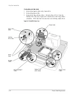
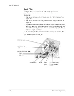
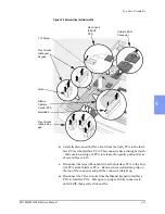
PCA. Pivot to make the underside visible as shown in
3. Connect the flex circuit from the SpO
2
connector to the SpO
2
PCA. Line
it up carefully, avoiding excessive twisting. There is no latch - just push
straight in. See Figure 4-23 on page 4-39.
4. Pivot the PCA down into position. Install the (2) T10 screws (see Figure
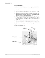
5. Align the connector and gasket with the notches in case and insert them in
the hole. Make sure the gasket is in place properly, between the connector
and the outside of the case.
6. Press in firmly on the connector to compress the gasket. Slide the metal
retainer clip into place behind the 2 plastic lugs on the connector, being
sure it locks into place. Use the new retainer clip that came with the con-
nector.
7. Restore the flex circuit to the Interface PCA back to its original position
against the bottom case. Secure with adhesive patch.
8. Replace and reconnect the ECG connector as described in "ECG Connec-
Summary of Contents for Heartstart XLT
Page 1: ...H E A R T S TA R T X LT S e r v i c e M a n u a l M 3 5 0 0 B M 5 5 0 0 B ...
Page 2: ......
Page 3: ...Service Manual M3500B HeartStart XLT M5500B Heartstart 4000 Defibrillator Monitor ...
Page 6: ......
Page 16: ......
Page 20: ......
Page 52: ......
Page 216: ......
Page 223: ......
Page 224: ...M3500 90900 Printed in USA February 2003 Second Edition M3500 90900 2 ...


