M3500B/M5500B Service Manual
4
-
39
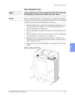
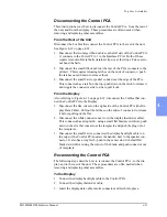
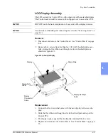
Top Case Assemblies
4
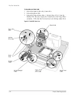
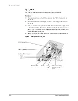
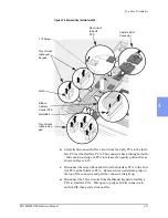
Figure 4-23 Disconnecting the SpO
2
PCA
Replacement
1. Using isopropyl alcohol, clean the case bottom where the ferrite will be
located (next to the end of the Interface PCA) and allow it to dry.
2. Gently unbend one end of the new flex circuit and slip the new ferrite on.
Then gently bend the flex circuit back to its original position. Do not kink
it sharply.
3. Connect one end of this flex circuit to the Interface PCA. Note the correct
orientation as shown in Figure 4-22 - the short tail connects to the Inter-
face PCA, and the long tail connects to the SpO
2
PCA .
4. Attach the adhesive patch onto the bottom of the ferrite.
5. Connect the other end of the flex circuit to the SpO
2
PCA.
6. Replace the SpO
2
connector and connect it to the SpO
2
PCA. See "SpO
Connector" on page 4-42.
7. Using the adhesive patch, secure the flex circuit and its ferrite in position
against the bottom case.
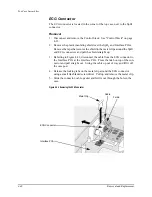
8. Replace and reconnect the ECG connector as described in "ECG Connec-
Flex Circuit From
SpO
2
Connector to
SpO
2
PCA
Flex Circuit From
SpO
2
PCA to
Interface PCA
SpO
2
PCA
Summary of Contents for Heartstart XLT
Page 1: ...H E A R T S TA R T X LT S e r v i c e M a n u a l M 3 5 0 0 B M 5 5 0 0 B ...
Page 2: ......
Page 3: ...Service Manual M3500B HeartStart XLT M5500B Heartstart 4000 Defibrillator Monitor ...
Page 6: ......
Page 16: ......
Page 20: ......
Page 52: ......
Page 216: ......
Page 223: ......
Page 224: ...M3500 90900 Printed in USA February 2003 Second Edition M3500 90900 2 ...

