Top Case Assemblies
4
-
44
Removal and Replacement
Manual Keypad Assembly
Should the Manual Keypad sustain a puncture or tear, it must be replaced in
order for the unit to be water resistant. The Manual Keypad assembly consists
of a heavy rubber overlay, and under that the membrane switches themselves.
Both parts are adhesive-backed, and replacing them consists of peeling up the
old, cleaning the surface, and sticking down the new.
CAUTION
See cautions regarding handling and connection of flex circuits on page 4-1.
Removal
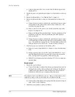
1. Disconnect and remove the Control Stack. See "Control Stack" on page
2. Remove the plastic insulating shield over the SpO
2
and Interface PCAs.
Remove the tape that secures the shield to the metal clips around the SpO
2
and ECG connectors and pull the shield straight up.
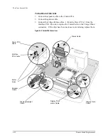
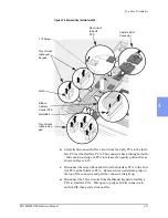
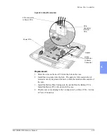
3. Referring to Figure 4-26, disconnect the 2 flex circuits from the Manual
keypad to the Interface PCA at the Interface PCA. Pull up on the top edge
of the white connector to unlatch the ZIF, then gently slide out the flex.
Disconnect only those 2, and leave all other connections to the Interface
PCA intact.
Figure 4-26 Manual Keypad Flex Circuits
Flex Circuits
to Manual
Keypad
T10 Screw
Summary of Contents for Heartstart XLT
Page 1: ...H E A R T S TA R T X LT S e r v i c e M a n u a l M 3 5 0 0 B M 5 5 0 0 B ...
Page 2: ......
Page 3: ...Service Manual M3500B HeartStart XLT M5500B Heartstart 4000 Defibrillator Monitor ...
Page 6: ......
Page 16: ......
Page 20: ......
Page 52: ......
Page 216: ......
Page 223: ......
Page 224: ...M3500 90900 Printed in USA February 2003 Second Edition M3500 90900 2 ...


