M3500B/M5500B Service Manual
4
-
37
Top Case Assemblies
4
LCD Display Assembly
The LCD is under the Control PCA, on the other side of the metal shield plate.
The Control stack should be removed, then flipped over to access the LCD.
CAUTION
DO NOT touch the back side (interior of case side) of the display window.
CAUTION
See the notes on handling and connecting flex circuits ("Servicing Notes" on
page 4-1).
Removal
1. Disconnect and remove the Control Stack. See "Control Stack" on page
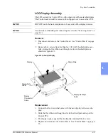
2. Remove the 4 screws from the Display. Lift it off the shield plate care-
fully, sliding the flex ribbon out through its slot in the shield plate as
shown in Figure 4-21.
Figure 4-21 Removing the Display
Replacement
1. Connect the flex circuit that came with the new display to the new dis-
play.
2. Slide the flex ribbon in through its slot in the shield plate and up to the
Control PCA.
3. Put display in place against the shield plate and install the 4 screws.
4. Replace and reconnect the Control Stack. See "Control Stack" on page 4-
Shield Plate
Display
Display Backlight
Cable
Display Data
Cable
Display
Thermistor
Cable
Summary of Contents for Heartstart XLT
Page 1: ...H E A R T S TA R T X LT S e r v i c e M a n u a l M 3 5 0 0 B M 5 5 0 0 B ...
Page 2: ......
Page 3: ...Service Manual M3500B HeartStart XLT M5500B Heartstart 4000 Defibrillator Monitor ...
Page 6: ......
Page 16: ......
Page 20: ......
Page 52: ......
Page 216: ......
Page 223: ......
Page 224: ...M3500 90900 Printed in USA February 2003 Second Edition M3500 90900 2 ...

