M3500B/M5500B Service Manual
4
-
65
Bottom Case Assemblies
4
Patient Connector
Removal
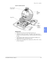
1. Disconnect the 3 connectors from the Patient Connector to the Power
PCA at the Power PCA - 2 are High Voltage spade connectors (note the
correct locations before removing) and 1 is a 9 pin connector with a latch.
See Figure 4-33.
2. Unscrew the large nut on the back of the connector.
3. Pull the connector and its wires and O-ring out of the case. Guide the 9
pin connector out through the nut and through the hole in the case by turn-
ing the connector sideways.
Replacement
1. Slide the wires of the new connector through the new O-ring that came
with the connector, then insert them through the hole in the case, and then
through the large nut. Use the existing nut.
2. Seat the O-ring on the connector.
3. Align the flat section on the connector with the flat portion of the case
hole.
4. Push the connector into the hole, seating the O-ring into the case.
5. Tighten large nut snugly but not excessively - the goal is to compress the
O-ring, not crush it hard against the case.
6. Replace the 3 connectors from the Patient Connector to the Power PCA.
Summary of Contents for Heartstart XLT
Page 1: ...H E A R T S TA R T X LT S e r v i c e M a n u a l M 3 5 0 0 B M 5 5 0 0 B ...
Page 2: ......
Page 3: ...Service Manual M3500B HeartStart XLT M5500B Heartstart 4000 Defibrillator Monitor ...
Page 6: ......
Page 16: ......
Page 20: ......
Page 52: ......
Page 216: ......
Page 223: ......
Page 224: ...M3500 90900 Printed in USA February 2003 Second Edition M3500 90900 2 ...

