M3500B/M5500B Service Manual
4
-
33
Top Case Assemblies
4
Control Stack
The Control Stack consists of the Control PCA, the metal shield plate to
which that mounts, and the Display, which is mounted on the back of the
shield plate. The steps below describe how to remove and replace the Control
Stack. This procedure is often needed when replacing other assemblies.
Removal
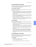
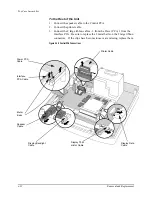
1. Disconnect the Control PCA from the rest of the unit. See "Disconnect-
ing the Control PCA" on page 4-31.
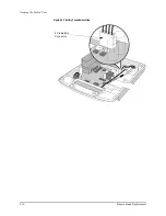
2. Remove the 5 T10 screws around the edge of the metal shield plate and
remove the Control Stack. See Figure 4-19. Lift it straight up out of the
case and lay it down, display side up, on a soft static-protected surface.
CAUTION
Removing the Control Stack exposes the back side of the Display Window.
Do not touch this side of the Display Window - fingerprints, etc. are very dif-
ficult to remove from its specially coated surface.
Replacement
1. Put the Control Stack back in place in the case.
2. Install the 5 screws in the shield plate. See Figure 4-19.
3. Reconnect the Control PCA to the rest of the unit (see "Reconnecting the
Control PCA" on page 4-31).
Figure 4-19 Removing the Control Stack
Shield
Plate
Control
PCA
Lithium Battery
Summary of Contents for Heartstart XLT
Page 1: ...H E A R T S TA R T X LT S e r v i c e M a n u a l M 3 5 0 0 B M 5 5 0 0 B ...
Page 2: ......
Page 3: ...Service Manual M3500B HeartStart XLT M5500B Heartstart 4000 Defibrillator Monitor ...
Page 6: ......
Page 16: ......
Page 20: ......
Page 52: ......
Page 216: ......
Page 223: ......
Page 224: ...M3500 90900 Printed in USA February 2003 Second Edition M3500 90900 2 ...

