


Connecting the Accessories
94
•
Connect the Signal Cable red lead to CELL SIGNAL and the black lead to SIG
COM.
3.
If you are installing an ElCD amplifier board (P/N N612-0060) in the Clarus 500 GC,
locate the External Amplifier Cable Assembly
(P/N N610-0187) supplied with the amplifier kit.
4.
Connect one end of the External Amplifier Cable Assembly to connector J2 on the
ElCD amplifier board that is installed in the Clarus 500 GC, and at the other end of
the cable connect the red lead to 10V FS and the black lead to SIG COM on the
Control Unit rear panel (top two connectors).
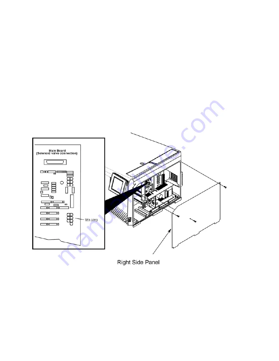
5.
Connect the solenoid vent valve cable to TE3 (J20) on the main board in the Clarus
500 GC electronics compartment behind the right side panel.
6.
Secure all cables in the existing cable clamps.
Figure 26. ElCD solenoid valve connection to TE3 on the Main Board in the Clarus 500
GC.
Summary of Contents for clarus 500 gc
Page 1: ...Clarus 500 GC Installation Guide ...
Page 5: ...Introduction 1 ...
Page 6: ......
Page 12: ...Introduction 12 Label locations on instrument ...
Page 13: ...Safety Practices 2 ...
Page 14: ......
Page 33: ...Preparing Your Laboratory 3 ...
Page 34: ......
Page 43: ...Clarus 500 GC Installation Guide 43 Sample Preparation Requirements Customer Responsibility ...
Page 45: ...Installing the Clarus 500 GC 4 ...
Page 46: ......
Page 58: ...Installing the Clarus 500 GC 58 ...
Page 59: ...Connecting the Gases and Electrical Supply 5 ...
Page 60: ......
Page 82: ...Connecting the Gases and Electrical Supply 82 Figure 22 Connecting the CO2 or LN2 supply ...
Page 84: ...Connecting the Gases and Electrical Supply 84 Table 2 Plugs Used in Different Countries ...
Page 88: ...Connecting the Gases and Electrical Supply 88 ...
Page 89: ...Connecting the Accessories 6 ...
Page 90: ......
Page 92: ...Connecting the Accessories 92 Figure 24 ElCD Control Unit front panel ...
Page 106: ...Connecting the Accessories 106 ...
Page 107: ...PPC Restrictor Information 7 ...
Page 108: ......


