


Clarus 500 GC Installation Guide
53
Install the Autosampler Tower Cover
Install the autosampler tower cover by referring to Figures 4 and 5 as you follow this
procedure:
1.
The tower is shipped with two 3/8-in. long screws installed on the bottom of the
tower frame. Loosen but do not remove these screws.
2.
Open the cover door and carefully lower the cover onto the tower, aligning the two
guides inside the cover with the sides of the tower (see Figure 5).
3.
Pull the sides of the cover away from the tower frame just enough to slide the
cover tabs onto the two screws.
4.
Tighten the two screws. Verify that the cover door opens and closes freely and that
it locks when closed. If not, realign the cover until the door locks when closed.
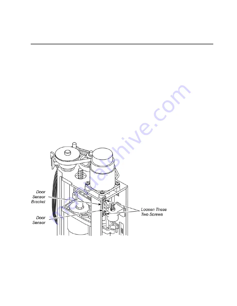
NOTE
:
If the door is hitting the door sensor, loosen the two screws that secure the door sensor
bracket to the tower, then adjust the sensor up or down until the door no longer hits the
sensor (see Figure 4).
Figure 4. Adjusting the position of the tower door sensor.
Summary of Contents for clarus 500 gc
Page 1: ...Clarus 500 GC Installation Guide ...
Page 5: ...Introduction 1 ...
Page 6: ......
Page 12: ...Introduction 12 Label locations on instrument ...
Page 13: ...Safety Practices 2 ...
Page 14: ......
Page 33: ...Preparing Your Laboratory 3 ...
Page 34: ......
Page 43: ...Clarus 500 GC Installation Guide 43 Sample Preparation Requirements Customer Responsibility ...
Page 45: ...Installing the Clarus 500 GC 4 ...
Page 46: ......
Page 58: ...Installing the Clarus 500 GC 58 ...
Page 59: ...Connecting the Gases and Electrical Supply 5 ...
Page 60: ......
Page 82: ...Connecting the Gases and Electrical Supply 82 Figure 22 Connecting the CO2 or LN2 supply ...
Page 84: ...Connecting the Gases and Electrical Supply 84 Table 2 Plugs Used in Different Countries ...
Page 88: ...Connecting the Gases and Electrical Supply 88 ...
Page 89: ...Connecting the Accessories 6 ...
Page 90: ......
Page 92: ...Connecting the Accessories 92 Figure 24 ElCD Control Unit front panel ...
Page 106: ...Connecting the Accessories 106 ...
Page 107: ...PPC Restrictor Information 7 ...
Page 108: ......


