


14
Node Address Settings and I/O Allocation
Section 2-2
Backup Trigger
(BACK, pin 4)
When pin 1 is ON (r
egistered table enabled)
and pin 4 is turned OFF to ON
, the
parameter data of all connected Slice I/O Units is backed up in the Communi-
cations Unit.
Note
The factory setting is OFF for all DIP switch pins.
2-2
Node Address Settings and I/O Allocation
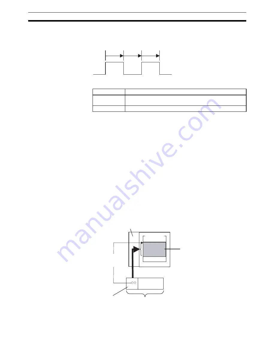
I/O words in the Master (the CPU Unit’s I/O memory) are allocated to the Slice
I/O Terminal based on the DeviceNet Communications Unit’s node address
setting. Once the DeviceNet node address is set, I/O will be allocated to the
Slice I/O Terminal by default and remote I/O communications will start auto-
matically.
Note
When the power is turned ON, unit numbers are allocated automatically to the
Slice I/O Units in the Slice I/O Terminal.
2-2-1
Setting the Node Address
The Slice I/O Terminal’s node address as a DeviceNet Slave is set with the
rotary switches on the front of the DeviceNet Communications Unit. The node
address determines the starting word of the area allocated to the Slice I/O
Terminal.
Switch setting
Function
ON
Switch ON to OFF to ON to start the parameter backup (when pin
1 is ON).
OFF
---
ON
OFF
ON
1 s
1 s
1 s
The backup operation starts after pin 4 is turned
from ON to OFF to ON within 3 seconds.
DeviceNet
Master Unit
Set the first allocated
word with the node
address setting.
I/O memory
Slice I/O
Terminal
CPU Unit
The DeviceNet Communications
Unit's DeviceNet node address
setting determines the first word
of the I/O memory area allocated
in the CPU Unit.
DeviceNet
Communications Unit
Slice I/O Terminal
Summary of Contents for SMARTSLICE - 04-2008
Page 1: ...DeviceNet Communications Unit Cat No W454 E1 03 SmartSlice GRT1 DRT OPERATION MANUAL ...
Page 2: ...SmartSlice GRT1 DRT DeviceNet Communications Unit Operation Manual Revised April 2008 ...
Page 3: ...iv ...
Page 5: ...vi ...
Page 13: ...xiv ...
Page 27: ...8 Basic Operating Procedure Section 1 5 ...
Page 57: ...38 Unit Functions Section 2 3 ...
Page 101: ...82 DeviceNet Explicit Messages Appendix A ...
Page 113: ...94 Standard Models Appendix C ...
Page 115: ...96 Power Consumption Tables Appendix D ...
Page 117: ...98 I O Current Consumption Appendix E ...
Page 119: ...100 Glossary ...


