General Description 2-25
LEDs
This section describes indications and meanings of the LEDs on NEC Express5800/ft series.
See “NAMES AND FUNCTIONS OF COMPONENTS” (pages 2-8 through 2-20) for the locations
of each LED.
POWER LED
This LED illuminates in green while the server is powered on. When power is off, this LED does
not illuminate. The LED also illuminates in green when one of CPU/IO modules is powered on.
DISK ACCESS LED
This LED indicates the status of hard disk drives loaded on 3.5-inch disk bays. Whenever the hard
disk drives are accessed, the LED blinks in green.
When this LED illuminates in amber, it indicates a hard disk drive has a problem. You can see the
status of the failed hard disk drive by checking the LED of each hard disk drive.
If this LED is blinking in amber, it indicates volumes in hard disk drives are not mirrored. See
“DISK OPERATIONS” (page 3-2) to configure mirror volumes.
FT Status LED
The LED stays green while the server is running normally in DUPLEX mode. If this LED does not
illuminate or illuminates/blinks in amber, there is something wrong with the server.
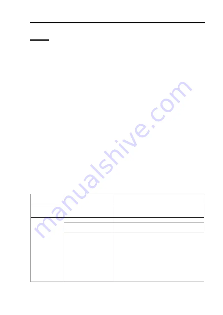
The table below shows indications of the FT Status LED and their meanings.
FT status LED
indications
Description Action
Green
The device is running
successfully in the Duplex
mode.
–
Power is off
–
Performing POST.
Wait for a while; it will illuminate in green and the
mode will become Duplex shortly after POST.
Not on
The device is running in
the Sipmlex mode
The LED indicates only one of modules is
running. If this status is observed right after the
system startup or activation of a module that has
been stopped, wait for a while. The status will
change to the Duplex mode with the LED lit in
green.
If the LED does not illuminate in green after a few
minutes, a device (LAN, FC-connected storage,
or internal disk) that should be redundant may not
be attached properly. Check to see devices to
make sure they achieve redundancy.
Summary of Contents for Express5800/320Fa-L
Page 2: ......
Page 19: ...Precautions for Use 1 3 Rack model Front Rear...
Page 45: ...General Description 2 13 Rack model with the front door open...
Page 48: ...2 16 General Description 27 HCS1 error LED See page 2 29 28 Heat warning LED See page 2 29...
Page 50: ...2 18 General Description Rear View Tower model Rack model...
Page 74: ...2 42 General Description This page is intentionally left blank...
Page 89: ...Windows Setup and Operation 3 15 7 Configure the mirror of the extended volume...
Page 107: ...Windows Setup and Operation 3 33 4 The confirmation dialog box appears Click Yes button...
Page 114: ...3 40 Windows Setup and Operation This page is intentionally left blank...
Page 141: ...System Configuration 4 27 Exit Move the cursor onto Exit to display the Exit menu...
Page 265: ...Installing and Using Utilities 5 65 Sample screen of Server Maintenance Utility...
Page 306: ...6 14 Maintenance This page is intentionally left blank...
Page 400: ...8 44 System Upgrade This page is intentionally left blank...
Page 404: ......
Page 405: ......


