4 - 23
4 POSITIONING DEDICATED SIGNALS
(b) M3213+20n : OFF
• If the drive module is a virtual servomotor or an incremental synchronous
encoder, operation will be continued from the current value within 1 virtual
axis revolution for the main shaft and auxiliary input axis in the previous
virtual mode.
• If the drive module is an absolute synchronous encoder, operation will be
continued from the current value within 1 virtual axis revolution for the
main shaft and auxiliary input axis calculated from the current value of
synchronous encoder.
(4) Cam reference position setting command (M3214+20n)
..................Command signal
This signal is only effective when the output module is a cam, and it is used to
specify the cam reference position.
The following processes are executed based on the ON/OFF state of the cam
reference position setting command at the real mode/virtual mode switching
request.
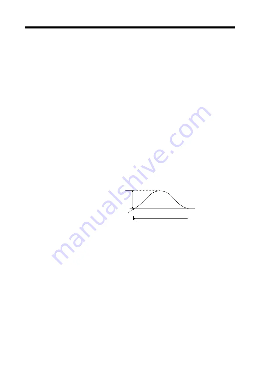
(a) M3214+20n : ON
• The current value is cam reference position.
• The current feed current value is lower stroke limit value (bottom dead
point). Moreover, a cam table search is conducted from the beginning of a
cycle, and the bottom dead point (0) is specified as the current value within
1 cam shaft revolution.
Stroke amount
0
Number of pulses within
1 cam shaft revolution-1
Lower stroke limit value
Feed current value
(bottom dead point)
when M3214+20n is ON.
1 cycle
Current value within 1 cam shaft revolution = 0
• After the bottom dead point alignment of cam is completed at the system
start-up, it must be turned on at the first real mode to virtual mode
switching.
Once the bottom dead point setting is set, operation will be continued with
M3214+20n ON by switching from real mode to virtual mode.
(The bottom dead point position is stored in the backup memory.)
Summary of Contents for Q Series
Page 1: ......
Page 19: ...A 18 MEMO ...
Page 129: ...4 90 4 POSITIONING DEDICATED SIGNALS MEMO ...
Page 134: ...5 5 5 MECHANICAL SYSTEM PROGRAM MEMO ...
Page 139: ...5 10 5 MECHANICAL SYSTEM PROGRAM MEMO ...
Page 163: ...6 24 6 DRIVE MODULE MEMO ...
Page 201: ...7 38 7 TRANSMISSION MODULE MEMO ...
Page 257: ...9 12 9 REAL MODE VIRTUAL MODE SWITCHING AND STOP RE START MEMO ...
Page 267: ...10 10 10 AUXILIARY AND APPLIED FUNCTIONS MEMO ...
Page 352: ......


