2 - 7
2 STARTING UP THE SYSTEM
2.3.4 Control change (Current value change/speed change/target position change)
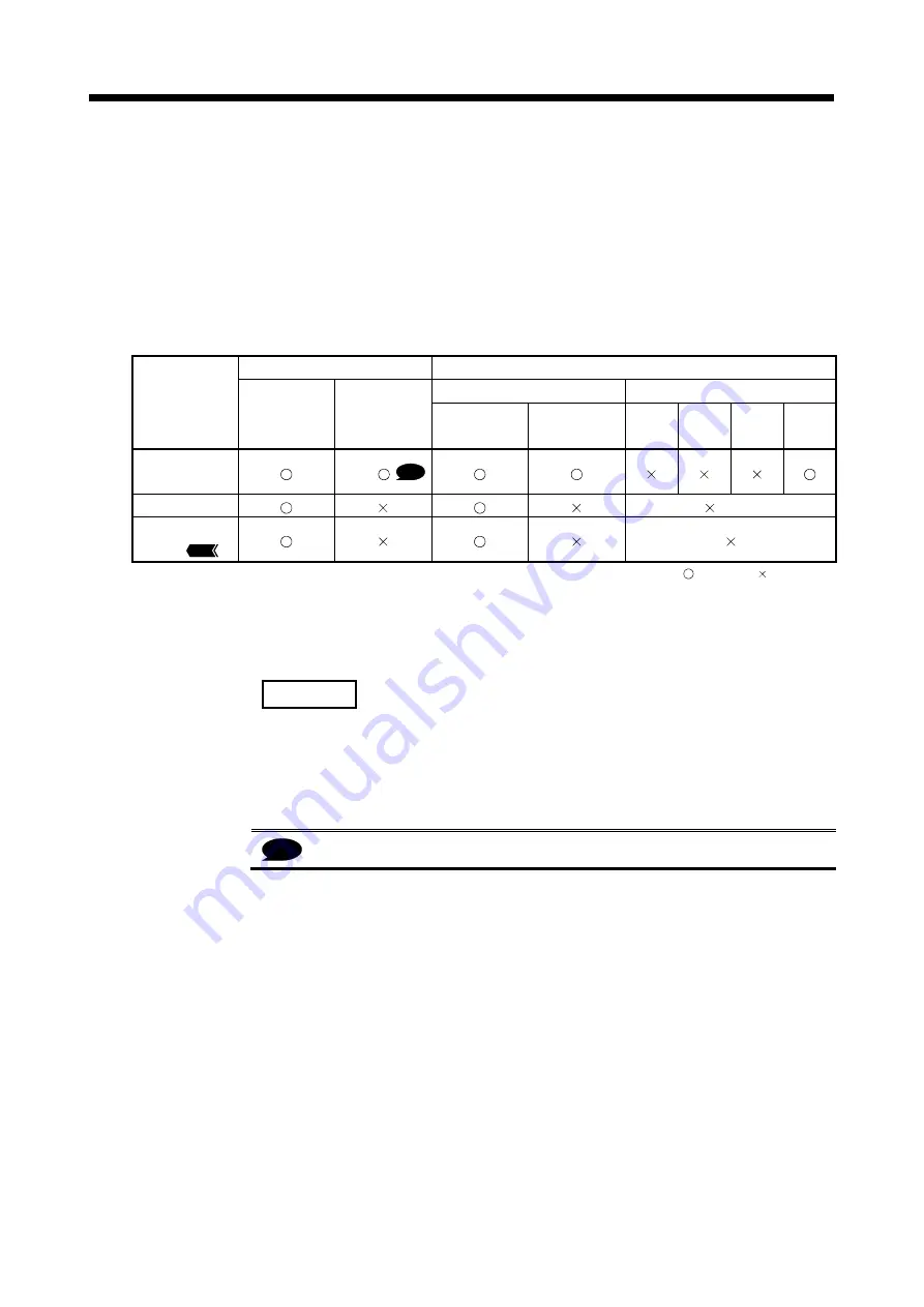
When a control change is executed in the virtual mode, the feed current value/speed of
the drive module is changed.
Control changes are not possible for the output module (except for cam).
Differences between control changes in the real mode and virtual modes are shown in
Table 2.4 below.
Table 2.4 Differences List of Control Change
Real mode
Virtual mode
Drive module
Output module
Item
Servo motor
Synchronous
encoder
Virtual servo
motor
Synchronous
encoder
Roller
Ball
screw
Rotary
table
Cam
Current value
change
Ver.!
Speed change
(Note-1)
Target position
change
QDS
: Used, : Unusable
(Note-1): If the output module is a roller which uses a speed change gear, a speed change can be executed by
changing the speed change gear ratio.
REMARK
Refer to the following Chapters for details of the drive and output modules.
• Drive module : Chapter 5 and 6
• Output module : Chapter 5 and 8
Ver.!
: Refer to Section 1.4 for the software version that supports this function.
Summary of Contents for Q Series
Page 1: ......
Page 19: ...A 18 MEMO ...
Page 129: ...4 90 4 POSITIONING DEDICATED SIGNALS MEMO ...
Page 134: ...5 5 5 MECHANICAL SYSTEM PROGRAM MEMO ...
Page 139: ...5 10 5 MECHANICAL SYSTEM PROGRAM MEMO ...
Page 163: ...6 24 6 DRIVE MODULE MEMO ...
Page 201: ...7 38 7 TRANSMISSION MODULE MEMO ...
Page 257: ...9 12 9 REAL MODE VIRTUAL MODE SWITCHING AND STOP RE START MEMO ...
Page 267: ...10 10 10 AUXILIARY AND APPLIED FUNCTIONS MEMO ...
Page 352: ......


