8 - 25
8 OUTPUT MODULE
(7) Program example
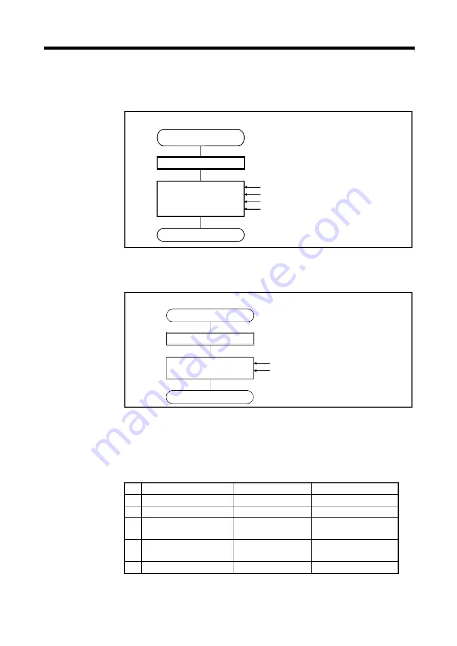
[Switching real mode/virtual mode]
Motion SFC program for switching real mode/virtual mode is shown below.
D2000=K1
D2002L=K50000
SET M3214
SET M2043
END
PX000*!M2043*!M2044
Switching real mode/virtual mode example
Switching
real mode/virtual mode
PX000 turn on, and real mode/virtual mode
switching request and switching status turn off.
Cam No. setting device set
Stroke amount setting device set
Cam reference position setting command set
Real mode/virtual mode switching request ON
G10
F10
(Note): Example of the above Motion SFC program is started using the automatic start or sequence program.
[Switching cam No./stroke amount during operation]
Motion SFC program for switching cam No. or stroke amount is shown below.
D2000=K1
D2002L=K60000
END
PX001
Cam data value setting example
Cam data value setting
Cam data value setting condition PX001
turn on.
Cam No. setting device set
Stroke amount setting device set
G10
F10
(Note): Example of the above Motion SFC program is started using the automatic start or sequence program.
8.4.2 Settings items at cam data creating
This section describes the setting items at cam data creating using MT Developer2.
Table 8.4 Table of Settings Items at cam Data Creating
No.
Setting item
Default
Setting range
1 Cam No.
—
Refer to (1)
2 Resolution
256
256, 512, 1024, 2048
3
Stroke amount/
Cam No. change point
0
0 to (resolution-1)
4 Operation mode
Two-way cam mode
• Two-way cam mode
• Feed cam mode
5 Cam data table
0
0 to 32767
Summary of Contents for Q Series
Page 1: ......
Page 19: ...A 18 MEMO ...
Page 129: ...4 90 4 POSITIONING DEDICATED SIGNALS MEMO ...
Page 134: ...5 5 5 MECHANICAL SYSTEM PROGRAM MEMO ...
Page 139: ...5 10 5 MECHANICAL SYSTEM PROGRAM MEMO ...
Page 163: ...6 24 6 DRIVE MODULE MEMO ...
Page 201: ...7 38 7 TRANSMISSION MODULE MEMO ...
Page 257: ...9 12 9 REAL MODE VIRTUAL MODE SWITCHING AND STOP RE START MEMO ...
Page 267: ...10 10 10 AUXILIARY AND APPLIED FUNCTIONS MEMO ...
Page 352: ......


