4. PARAMETERS
4 - 25
No./symbol/
name
Setting
digit
Function
Initial
value
[unit]
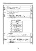
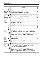
PT17
LMNL
Software limit
-
(lower four
digits)
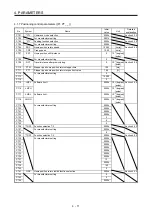
Set an address decreasing side of the software stroke limit.
Upper and lower are a set.
Set an address in hexadecimal.
Setting address:
Upper four
digits
Lower four
digits
[Pr. PT17]
[Pr. PT18]
Setting a same value with "Software limit +" will disable the software stroke limit. (Refer to section
4.3.)
When changing the setting with the parameter, change it during servo-off, in the homing mode,
velocity mode, or torque mode.
In the position mode during servo-on, changing the setting in a certain order may trigger [AL. 35],
[AL. 69], or [AL. 98].
This function will be enabled in the profile mode and cyclic synchronous mode.
The unit can be changed to 10
-3
[degree] or [pulse] with the setting of [Pr. PT01].
This parameter corresponds to "Min position limit (Index: 607Dh, Sub: 1)". When this parameter is
mapped to the link device of CC-Link IE Field Network Basic, the value written with MR
Configurator2 is overwritten by the controller. Thus, do not write a value with MR Configurator2.
Setting range: 00000000h to FFFFFFFFh
0000h
Refer to
Function
column
for unit.
PT18
LMNH
Software limit
-
(upper four
digits)
0000h
Refer to
Function
column
for unit.
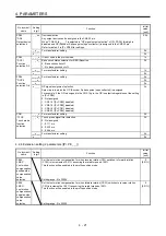
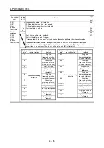
PT26
*TOP2
Function
selection T-2
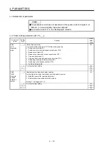
_ _ _ x Electronic gear fraction clear selection
0: Disabled
1: Enabled
Selecting "Enabled" will clear a fraction of the previous command by the electronic gear at start of
the profile mode.
0h
_ _ x _ For manufacturer setting
0h
_ x _ _
0h
x _ _ _
0h
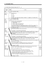
PT29
*TOP3
Function
selection T-3
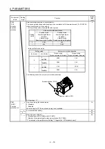
Set the DOG polarity.
_ _ _ x
(HEX)
_ _ _ x (BIN): DOG (Proximity dog) polarity selection
0: Dog detection with off
1: Dog detection with on
0h
_ _ x _ (BIN): For manufacturer setting
_ x _ _ (BIN): For manufacturer setting
x _ _ _ (BIN): For manufacturer setting
_ _ x _ For manufacturer setting
0h
_ x _ _
0h
x _ _ _
0h
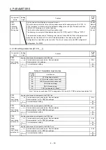
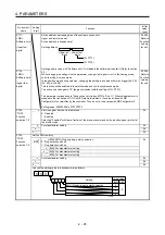
Convert the setting value into hexadecimal as follows.
0
Initial value
BIN HEX
Setting
0
0
0 0
0
0
0
DOG (Proximity dog) polarity selection
Summary of Contents for MELSERVO-JE
Page 15: ...1 FUNCTIONS AND CONFIGURATION 1 4 MEMO ...
Page 21: ...2 SIGNALS AND WIRING 2 6 MEMO ...
Page 57: ...4 PARAMETERS 4 34 MEMO ...
Page 109: ...6 SERVO MOTOR DRIVING 6 44 MEMO ...
Page 111: ...7 APPLICATION OF FUNCTIONS 7 2 MEMO ...
Page 113: ...MEMO ...

