Graphic Operation Terminal F930GOT
Introduction 1
1-14
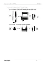
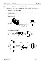
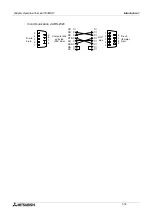
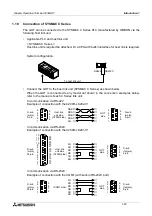
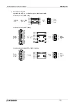
Pin layout and connection diagram of connection cables
(Connection cables are offered as options.)
-
Connection cables FX-40DU-CAB(-10M/-20M/-30M) and FX-50DU-CABL
-
Connection cable FX-50DU-CAB0(-1M/-10M/-20M/-30M)
D-sub
(male),
25-pin
PLC side
13
GOT
side
D-sub
(male),
9-pin
12
11
10
9
8
7
6
5
4
3
2
1
25
24
23
22
21
20
19
18
17
16
15
14
5
4
3
2
1
9
8
7
6
➀
➁
➃
➄
➅
➂
➁
➂
➄
➆
➃
➆
➇
➈
➇
15
21
16
17
18
MINI-DIN
(male),
8-pin
PLC side
GOT
side
D-sub
(male),
9-pin
1
2
3
4
5
6
7
8
➀
➁
➃
➄
➅
➆
➈
➁
➆
➅
➂
➀
➃
➄
5
4
3
2
1
9
8
7
6
Summary of Contents for F930GOT-BWD-E
Page 1: ...USER S MANUAL F930GOT BWD E ...
Page 4: ...Graphic Operation Terminal F930GOT ii ...
Page 6: ...Graphic Operation Terminal F930GOT iv ...
Page 14: ...vi ...
Page 60: ...Graphic Operation Terminal F930GOT Start up 2 2 10 MEMO ...
Page 68: ...Graphic Operation Terminal F930GOT Screen Mode 3 3 8 MEMO ...
Page 120: ...Graphic Operation Terminal F930GOT Creation of Display Screens 8 8 30 ...
Page 200: ...Graphic Operation Terminal F930GOT Changeover of Display Screen FX PCS DU WIN E 10 10 18 ...
Page 272: ...Graphic Operation Terminal F930GOT Additional Functions in V 2 00 or later 13 13 24 MEMO ...


