Graphic Operation Terminal F930GOT
Creation of Display Screens (FX-PCS-DU/WIN-E) 9
9-19
9.4.3
Bar Graph
The "Bar Graph" object displays the value of a specified word device (current value/set value of
T or C or D, V or Z) in the PLC in the form of bar graph.
A numeric which is rather difficult to understand in the form of number can be displayed in the
form of bar graph so that it can be easily understood at a glance.
u
u
u
u
Contents of setting
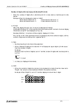
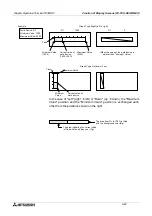
1) Graph Type
•
Bar graph type
Right (left
à
right)Up (down
à
up)
Left (right
à
left)Down (up
à
down)
•
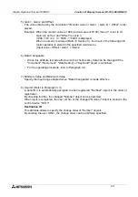
The value entered to "Minimum Value" is regarded as the 0% value. The value entered to
"Maximum Value" is regarded as the 100% value. The value of the specified word device
is represented in %.
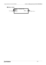
If the value of the specified word device is outside the range specified by "Minimum
Value" and "Maximum Value", a diagonal line is drawn in the bar graph.
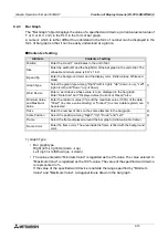
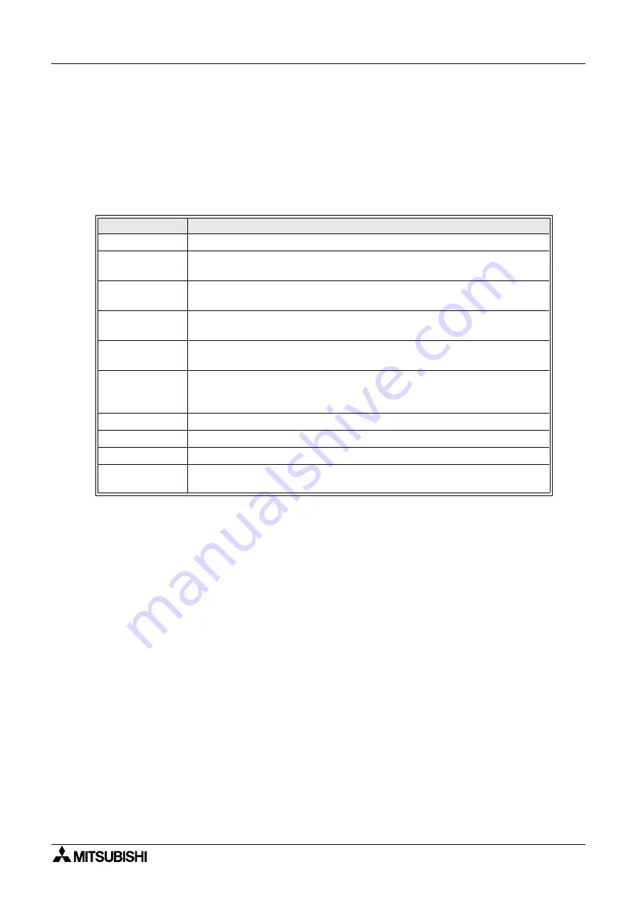
Attribute
Contents of setting
Position
Enter the X and Y coordinates in the unit of dot.
Size
Enter the width (W) and the height (H) of the bar graph in the unit of dot. The
allowable minimum value is 8 W x 16 H.
Bg and Fg
Enter the background color and the display color. (Initial values: White and
black)
Graph Type
Select the graph type among "Right" (left
à
right), "Up" (down
à
up), "Left"
(right
à
left) and "Down" (up
à
down).
1)
Word Device
Enter a word device whose value is to be displayed in the bar graph.
Enter "Data Size" and "Displayed value (Current or Preset)" also.
Minimum Value
and Maximum
Value
Enter the minimum value (0%) and the maximum value (100%) of the data.
"Direct" (to enter a value directly) or "Indirect" (to enter a data register) can
be selected.
1)
Ticks
Enter the number of ticks on the scale attached to the bar graph.
2)
Scale Position
Select the position among "Right", "Up", "Down" and "Left".
2)
Frame
Select the frame displayed around the bar graph. (Initial value: No frame)
Frame Color
Enter the frame color. The area inside the frame is filled with the background
color.
Summary of Contents for F930GOT-BWD-E
Page 1: ...USER S MANUAL F930GOT BWD E ...
Page 4: ...Graphic Operation Terminal F930GOT ii ...
Page 6: ...Graphic Operation Terminal F930GOT iv ...
Page 14: ...vi ...
Page 60: ...Graphic Operation Terminal F930GOT Start up 2 2 10 MEMO ...
Page 68: ...Graphic Operation Terminal F930GOT Screen Mode 3 3 8 MEMO ...
Page 120: ...Graphic Operation Terminal F930GOT Creation of Display Screens 8 8 30 ...
Page 200: ...Graphic Operation Terminal F930GOT Changeover of Display Screen FX PCS DU WIN E 10 10 18 ...
Page 272: ...Graphic Operation Terminal F930GOT Additional Functions in V 2 00 or later 13 13 24 MEMO ...


