POWER CORE User Manual
Version: V6.0.0/5
185/459
13. Control Surface Configuration
13.2
Panel Selection
1.
From the main menus, select
Frame -> Surface
to define the layout of your control surface modules.
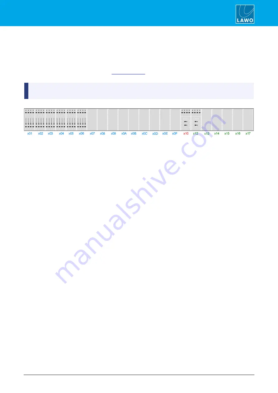
If this is a new configuration, then the Surface appears as a series of empty cover plates except for the
compulsory Central Module.
The maximum frame size is defined by the
. For larger frames you may need to scroll to the right
to see the Central Module.
Each module position represents a CAN bus address within the frame. The CAN bus address, otherwise
known as the Frame ID, is a unique address which defines the role of each module within the system.
CAN Bus Addresses (hexadecimal)
2.
Right-click on a position to assign a module.
The options for each hexadecimal CAN Bus address are:
·
Address 01 to 0F
= Fader Module (1 to 15) or a blank panel:
o
Addr 01
= Faders 1-4 (Layer 1) & 5-8 (Layer 2)
o
Addr 02
= Faders 9-12 & 13-16
o
and so on up to..
o
Addr 0F
= Faders 113-116 & 117-120
·
Address 10
= the main Central Module. Every layout includes this assignment.
·
Address 12
to
17
= Central Module 1 to 6 (in monitor mode) or a blank panel.
3.
Select an option and left-click to confirm - the Surface updates to show the assigned module.
4.
Repeat the process to assign each position within the Surface frame.
Note that the
Frame
->
Surface
window will not necessarily look like your physical console, as it is the CAN bus
addresses which are important.
What is important is that the CAN bus address set on the module matches your configuration. You can check the
CAN bus address on individual modules using the special functions mode.
5.
If you double-click on a Module, you will open its parameter window.


