background image

POWER CORE User Manual

Version: V6.0.0/5

405/459

20. Maintenance

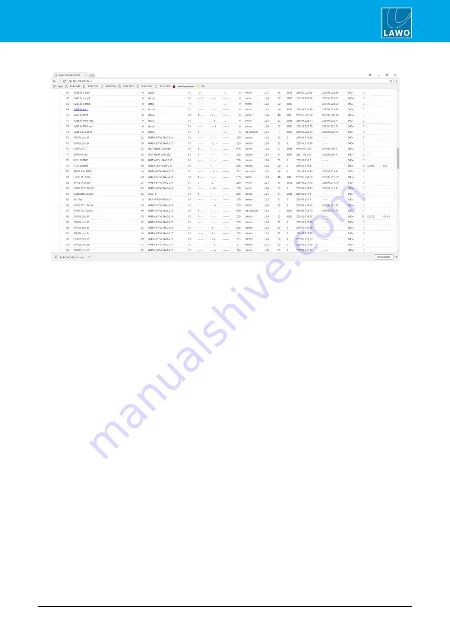
Streams Tab

The Streams diagnostic table shows a list of all available network streams which have been announced to the
Power Core. You can click on any stream name to expand it and gain additional information, such as SDP data,
explanation of flags which indicate error conditions, and destinations for active streams.

Summary of Contents for POWER CORE

Page 1: ...POWER CORE User Manual Version V6 0 0 5 To obtain the latest documentation and software downloads please visit www lawo com downloads Edition 21 May 2018 ...

Page 2: ...ners It cannot be guaranteed that all product names products trademarks requisitions regulations guidelines specifications and norms are free from trade mark rights of third parties All entries in this document have been thoroughly checked however no guarantee for correctness can be given Lawo AG cannot be held responsible for any misleading or incorrect information provided throughout this manual...

Page 3: ... 5 Setting the IP Address 24 5 6 Getting Operational 25 5 7 Wiring 26 5 8 Synchronisation 31 6 Licensing 33 6 1 Licensed Feature Sets 34 6 2 Working with the License System 36 7 Configuring POWER CORE 46 7 1 Starting a Configuration 47 7 2 Creating a New Configuration 48 7 3 Opening an Existing Configuration 50 7 4 Loading a Project from the Unit 51 7 5 Selecting a Different License Package 52 7 6...

Page 4: ...g Loopbacks 143 10 2 GP Sums 145 10 3 Direct Outs 146 11 Routing Matrix 147 11 1 Routing Matrix Anatomy 148 11 2 Crosspoint Switching 149 11 3 Saving Crosspoints in Snapshots 157 12 Intercom 158 12 1 InterCom System Introduction 159 12 2 InterCom Local vs InterCom Net 160 12 3 System Configuration 161 12 4 InterCom Software 170 13 Control Surface Configuration 183 13 1 Frame Selection 184 13 2 Pan...

Page 5: ...Control 247 15 2 Access to Control Surface Parameters 249 15 3 Fader Strip Assignment 250 15 4 DSP Parameter Control 253 15 5 Fader Strip ACCESS Keys 254 15 6 Monitoring Signal Switcher 255 15 7 Talkback Controller 257 15 8 Routing Matrix Control 259 15 9 Advanced VisTool Integration 265 15 10 Timers 272 15 11 General Settings 273 16 Key Panel Control 274 16 1 Key Panel Options 275 16 2 Adding Key...

Page 6: ...314 18 14 Logic Macro 315 18 15 Logic MFF Mono Flip Flop 336 18 16 Logic MOM LAT Momentary Latch 337 18 17 Logic Mon Desk 338 18 18 Logic MUX DEMUX 8 339 18 19 Logic NOT 340 18 20 Logic OR8 341 18 21 Logic OR32 343 18 22 Logic PRIO 344 18 23 Logic TB State 345 18 24 Logic Text Prio 346 18 25 Logic TFF Toggle Flip Flop 348 18 26 PowerUp Control Outputs 349 18 27 Ember Logical Functions 350 19 Netwo...

Page 7: ...ive Parts 423 20 5 Alarm Management 424 21 Trouble shooting 427 21 1 Boot up Issues 428 21 2 Hardware Power Issues 429 21 3 IP Networking Issues 430 21 4 Configuration Issues 431 22 Appendices 432 22 1 Part Numbers 433 22 2 Dimension Drawing 434 22 3 Connector Pin Outs 435 22 4 The 12V DC Power Supply 438 22 5 Default TCP IP Settings 439 22 6 Matrix Numbers 440 22 7 Mackie HUI Parameters 441 22 8 ...

Page 8: ... or as the integrated DSP Core for a Lawo control surface If installing with a control surface you will find more information on the surface components in the relevant manual All Lawo manuals are available from the Download Center at www lawo com after Login Look out for the following which indicate Notes points of clarification Tips useful tips and short cuts WARNINGS Alert you when an action sho...

Page 9: ...filled with liquids such as vases upon a device Only service staff may replace batteries CAUTION Danger of explosion if battery is incorrectly replaced Replace only with the same or equivalent type Servicing of components inside a device MUST only be carried out by qualified service personnel according to the following guidelines Before removing parts of the casing shields etc the device MUST be s...

Page 10: ...efore sending parts for repair Please contact our service department before sending parts for repair First Aid in the case of electric shock DO NOT touch the person or his her clothing before power is turned off otherwise you risk sustaining an electric shock yourself Separate the person as quickly as possible from the electric power source as follows Switch off the equipment Unplug or disconnect ...

Page 11: ...ely a guide as one of the Radio Console packages could also be suitable for a stand alone system The license must be installed onto a USB memory stick and connected to the DONGLE port The Configuration All programmable functions are defined by the system configuration This is stored on the control system and read during boot up The configuration can be edited using the ON AIR Designer software The...

Page 12: ...RE User Manual Version V6 0 0 5 12 459 4 The Hardware 4 The Hardware This chapter describes the hardware including all options and accessories Topics include Controls Indicators Connectors IO Cards Accessories ...

Page 13: ...S 422 Serial This port can be used for remote control of POWER CORE MACKIE HUI interfacing to a Digital Audio Workstation and for debugging 7 ETHERNET 1 Gigabit Ethernet Control Connects other devices to the POWER CORE control system Applications include remote control via TCP IP networking to other products updating firmware and the configuration 8 ETHERNET 2 3 AES67 RAVENNAIP Streaming Connects ...

Page 14: ...n AC provides the main and DC the redundant power supply WARNING POWER CORE MUST be connected to the mains using the power cable supplied with the system 4 1 1 The Front Panel Display Front View The front panel display can be used to view local device parameters 1 Turn the rotary control to step through the available pages Each page includes a blue title field Welcome Product etc Useful parameters...

Page 15: ...ting LED steady state and not white the device has an internal problem The table below describes all possible states LED Color Status if LED is Steady State Status if LED is Blinking Blue System failure Synchronized to PTP master Yellow System failure Trying to sync to PTP master Red System failure Synchronized to internal clock Green System failure Synchronized via Wordclock Magenta System failur...

Page 16: ...POWER CORE These must be fitted to even numbered expansions slots only the top row There are no limitations when fitting the other card types All IO cards are optional and must be ordered separately To use your cards they must be installed into the frame see Fitting the IO Cards When ordering please use the following part numbers IO Card Part Number Description Max per Frame MIC LINE IN 710 20 8 x...

Page 17: ...OWER CORE license onto the USB dongle before connecting it to the device The license code for your chosen feature set can be found on the delivery note Optional The following accessories must be ordered separately 1 x external 12V DC power supply 955 50 80 with 2m IEC power cable country specific to connect 12V DC power to the frame 1 x USB license dongle safety cap SFP Module MADI 1310nm MM LC Du...

Page 18: ...6 0 0 5 18 459 5 Installation 5 Installation This chapter describes how to install the system Topics include Preparation Fitting the IO Cards Fitting the MADI SFP Modules Powering the Device Getting Operational Wiring Synchronisation ...

Page 19: ...rs are located at the front and rear of the unit Therefore when using 19 inch racks with doors please leave enough room for the cables If you have IO cards to install then these should be fitted BEFORE installing the unit into the rack Dimensions and Weight Width 482 6 mm 19 Height 44 0 mm 1 RU Depth housing only Depth inc front plate connectors 353 mm 382 mm Weight without IO cover plates fitted ...

Page 20: ... operational All cards are hot pluggable and so the exchange can be performed while the device is powered To remove and replace the screws you will need a small flat blade screwdriver not supplied Warning The IO cards carry highly sensitive electronic components and should be handled with care ALWAYS observe the following procedures Discharge yourself before touching an IO card Wear conductive saf...

Page 21: ...x the card in place CAUTION ALWAYS secure the IO card using the screws provided This protects the operator from contact with live parts protects the card from being pulled out unintentionally and reduces the emission of electro magnetic radiation 5 When you have fitted all the IO cards for your system check that all cards are screwed into the frame and that any empty slots are closed with metal co...

Page 22: ...an be fitted or exchanged while the device is powered 1 Remove the dust caps from both the port and SFP module Store these carefully so that they can be replaced if a module is removed 2 Push the SFP module into the rectangular slot 3 Press gently and firmly until the module locks into position Warning Before removal please unlock SFP modules to avoid mechanical damage to the slots If a module is ...

Page 23: ...e end of boot up process POWER CORE loads its warm start data This is the state of all settings at the last shut down It means that when you turn on you will get back to wherever you were at the last power off Note that the last known PTP Master Slave mode may not be reinstated if POWER CORE is set to operate as PTP Slave only Please note if you load a new configuration or perform a firmware updat...

Page 24: ...rent IP settings assigned to the three Ethernet ports The top entry dwc0 corresponds to front panel port 1 and is used for system administration and control Any of the fields marked with an asterisk can be edited You will need to enter the Administrator password in order to modify the parameters 3 To change the IP Address click in the IP Address field and type in the new IP 4 Then click on Apply t...

Page 25: ... 2 Transfer a configuration onto the device To get the system working you will need to transfer a suitable configuration using the ON AIR Designer Start the software and open the project Then transfer the configuration to the device You will find full details on these procedures in the separate ON AIR DESIGNER User Guide Once the transfer is complete POWER CORE will cold start and load the configu...

Page 26: ...ated wide ranging AC power supply and is delivered with a 2m IEC power cable country specific Using the IEC cable provided 1 Connect your mains to the 100 240V AC input on the rear panel DC Input To use the DC input you will need the external 12V DC power supply this is optional and must be ordered separately 12V DC Power Supply 955 50 80 For dimensions weight and electrical specification see the ...

Page 27: ...oss of signal quality 5 7 3 CAN Bus If POWER CORE is installed with a control surface then the CAN bus is used to connect the control surface frames If there are no control surface components then this connector is unused All control surface components should be connected to the CAN bus in a daisy chain fashion starting from the POWER CORE For specific instructions please refer to your control sur...

Page 28: ... 1 network cable The cable should be STP CAT 5 with RJ45 connectors When using a crossed network cable direct connection the Use of a Proxy Server browser option must be deactivated Otherwise access is prevented by looking for a Proxy Making the Connection 1 Connect your remote device either directly or via a network switch to the ETHERNET 1 port of POWER CORE 2 To establish communication configur...

Page 29: ...ADI The four MADI ports on the front panel and any optional MADI on rear IO cards can be used to connect multi channel digital audio to an external device Each port provides 64 bi directional MADI AES10 channels Dual redundant ports and the number of transmitted channels 56 or 64 can be defined by the ON AIR Designer To use the MADI ports you must fit a Lawo certified SFP module The SFP determines...

Page 30: ...closures GPI 8 x optocouplers 3 36 VDC 8mA 36V GPO 8 x silent CMOS relays 50V AD DC 0 5A AC 1 0A DC The connector is a 37 pin D type See the Connector Pin Out for details 5 7 10 IO Cards All rear panel IO cards except MADI break out on DB 25 connectors that are wired according to the AES59 TASCAM standard See the Connector Pin Outs for details ...

Page 31: ... automatically By disabling all external sync options POWER CORE can act as a sync master and distribute its internal clock via PTP Wordclock or MADI to other devices Please note if POWER CORE has been synchronized once to a PTP master then it will NOT automatically switch to another sync source but try to re establish its connection to the external PTP master While doing this it becomes PTP maste...

Page 32: ...nal has been detected and Active The color coding indicates Blue sync source is enabled present and active Green sync source is enabled and present but not currently active Red sync source is enabled but not present The Prio Sequence box shows the priority of the external sync sources as defined by the configuration in our example PTP Wordclock and then MADI Sync Output The front panel WCLK OUT co...

Page 33: ...r Manual Version V6 0 0 5 33 459 6 Licensing 6 Licensing This chapter describes the licensed feature sets and how to work with the licensing system Topics include Licensed Feature Sets Working with the License System ...

Page 34: ...production console If used stand alone it offers extensive capabilities as large scale networkable DSP signal supervisor and router or intercom matrix 6 1 1 Signal Processing Resources Use the following as a guide to the Audio Processing entries in the POWER CORE License Chart Parallel Input sources are fully featured input channels with input gain signal presence indicator direct out insert fader...

Page 35: ...ith DSP EQ DYN LIM LOUDNESS 16 48 96 AutoMix DeEsser units 8 16 32 AutoMix Groups 1 2 4 Busses no processing 20 40 80 Bus processing DSP blocks EQ DYN LIM 0 16 32 PFL Busses 1 2 5 VCA Groups 0 1 8 5 1 Mixing and Processing NO NO YES Utility Tool MiniMixer 64 64 64 Patchable Meters PPM LOUDNESS Silence Detects 128 128 256 CONTROL KSC PANEL support YES YES YES VisTool control YES YES YES NETWORKING ...

Page 36: ...on the delivery note shipped with the system It takes the form of a 25 digit ticket number such as the one shown below License Code Example Once activated it is strongly recommended that you backup your licenses using the CodeMeter WebAdmin portal This will allow you to restore a license if the original dongle is lost or damaged The dongle is a specially configured USB memory stick which can be pu...

Page 37: ... the PC s USB port 1 Open the Lawo licensing web portal by copying the following URL into your web browser https licenseportal lawo com 2 Copy your license ticket number this is the 25 digit number code into the Ticket field and select Next 3 The WebDepot searches for and displays your licenses select Activate Licenses to continue 4 At the next page select the storage method for your license note ...

Page 38: ...tore multiple licenses in the same container If no Cm containers are available then you will see an option to Get CmContainer automatically 6 Click on Activate Selected Licenses Now and wait for a few seconds a confirmation pop up appears once the activation is successful 7 After selecting OK a summary appears 8 You can now close your web browser and install your USB license dongle ...

Page 39: ...memory stick to the DONGLE port on the front panel Note that an optional safety cap can be fitted to prevent accidental removal of the dongle If fitted you will need a T10 star tool to remove or fit the cap All licensed features should now be available If a valid license is not found then the alarm will sound every few seconds ...

Page 40: ... portal and copy the license update file back to the original computer Import the license update file to the Cm storage container Creating the License Request File On the computer you wish to license 1 Open the CodeMeter Control Center by clicking on the Cm taskbar icon and select the container you wish to use for the license storage 2 If the container is empty select Activate License Or if the co...

Page 41: ... Select Add license of a new producer Enter the Lawo FirmCode 102037 4 Select Next and using Windows Explorer enter a file path for the license request file Choose somewhere easy to find such as the Desktop Then select Commit to create the request file 5 Select Finish and copy the request file onto a computer with internet access You will need both the license request file and the 25 digit ticket ...

Page 42: ...the Lawo License web browser page at https licenseportal lawo com Copy your license ticket number this is the 25 number code into the Ticket field and select Next When your license is displayed select Activate Licenses to continue Select the storage method for your license either USB dongle or single computer 2 At the Available Licenses page select Offline license transfer to continue ...

Page 43: ...lorer choose the request file created earlier 4 Then select Upload Request And Continue Now the license request is processed and if successful you will have the option to Download the update 5 Select Download License Update File Now and when prompted choose the Save file option the file is downloaded 6 Copy the License Update file back to the original PC ...

Page 44: ...ust be the same container as the one selected earlier during the License Request 2 Select License Update and follow the instructions given by the CmFAS Assistant when prompted select Import License update and choose the update file downloaded from the License portal 3 Select Commit to action the update the license is activated and you can close the CodeMeter Control Center 4 You can now install yo...

Page 45: ...ultiple Lawo products or software versions you will see several LAWO AG containers In addition if a USB dongle is connected you will see a container labelled CmStick Local Computer Container LAWO AG USB Dongle Container CmStick The Serial numbers identify each container The icon colours indicate green license activated grey container is empty red license deactivated A single Cm container can conta...

Page 46: ...ld be familiar with the ON AIR Designer configuration tool If not please refer to the separate ON AIR Designer User Guide Topics include Starting a Configuration Creating a New Configuration Opening an Existing Configuration Loading a Project from the Unit Selecting a Different License Package Saving the Project Transferring Configuration Data to the Unit ...

Page 47: ...sfer the modified configuration back to the system Note that a copy of the project file can be stored on the POWER CORE device In this instance you can download a copy to your computer using Load Project from unit If you do not have access to an existing project then use File New to create a new configuration project If you plan to install VisTool s it is a good idea to create the VisTool and syst...

Page 48: ...te the number of Fader Modules Central Module Central Modules running in monitor mode Panels the maximum number of Key Panels connected to the system Screen is always set to Screen functions to support VisTool functions For the System Core please select the licensed package which has been purchased For the Surface select the maximum configuration required For example the ruby 16 Fader 4 1 option c...

Page 49: ...oftware creates the new configuration and a number of windows will open In our example we can see the Project window on the left plus the System Core in the central working area Note that it may take a few seconds to build the new project During this time the status is shown in the progress bar below Console in the Project window ...

Page 50: ...ct opens with the same workspace layout and docking options as at the last file save If the configuration was created using a different definition version then you may be asked if you wish to convert the project Note that it may take a few seconds to open the project During this time the status is shown in the progress bar below Console in the Project window If you see an error stating that the pr...

Page 51: ... supported by your system If you tick the option then a compressed version of the project file db3 or mdb will be transferred to the unit To download a project which has been previously transferred 1 Select File Load Project from unit If this option is greyed out then there is no network communication between your PC and the control system 2 A pop up appears enter the IP Address of the control sys...

Page 52: ...e frame to open the dialogue box Frame selection window Here you can specify each of the system components System Core Surface Panels or Screen as described earlier 2 If you change an option click on OK the software now loads the hardware configuration for the new frames Note that it may take a few seconds to load the data During this time the status is shown in the progress bar below Console in t...

Page 53: ...se the keyboard shortcut CTRL S This overwrites the existing project as specified in the File field in Project window Ø File Save As 1 Select File Save As from the top menu bar or use the keyboard shortcut CTRL SHIFT S the Save dialogue box opens 2 Choose a new folder location enter a different file name or select a different file type using the Files of type option at the bottom of the dialog box...

Page 54: ...hen use Transfer Setup to unit all products except POWER CORE or the Web UI POWER CORE 4 If you have made any changes to the configuration then these must be saved before the configuration is transferred Use either File Save or File Save As to save the project You can use any file name and location as long as the file type db3 remains unchanged 4 Select Transfer Config to unit from the top menu ba...

Page 55: ...is shown in the Console status area at the bottom of the Project window Once the transfer is complete you will see the lines File loaded to unit and Sending Restart The system may take a few seconds to restart Once boot up is complete the new configuration parameters should be valid Project Save Binary Files Creation Files Transferred to Unit If your computer s firewall prevents the transfer then ...

Page 56: ...User Manual Version V6 0 0 5 56 459 8 Audio IO 8 Audio IO This chapter describes how to configure the audio IO Topics include Setting Up IO Cards Setting Up RAVENNA AES67 Setting Up MADI Setting Up Synchronisation ...

Page 57: ... Selection Therefore if the Core does not look as expected please check the current specification You can zoom in or out on by pressing and holding CTRL while scrolling your mouse wheel If you double click on the text GT or DMS you will open parameter windows for GT used to send GPIO over audio DMS used for VisTool metering or to create audio loopbacks 2 To add or change a plug in card right click...

Page 58: ... Audio Input and Audio Output branches of the Tree Definition and selecting the appropriate IO card 8 1 2 Audio Card Parameters For each audio signal the available parameters depend on the IO card type Use the tabs to switch between the different parameter sets Input Output etc Module Parameters Every IO card includes a Module tab with the following option Ignore Card If enabled the IO card is ign...

Page 59: ... are three options in the drop down menu ON sets the input for Matrix Connect or Matrix Query functions or external matrix control such as the MtxCon NovaConnect software LS sets the input for control from the optional Line Scheduler LS product Please contact your local Lawo representative for details OFF the input is not enabled for external matrix control After a cold start any inputs set to Mat...

Page 60: ...is field to name the input as described earlier Type Stereo Use the Type and Stereo fields to set the format of the input as described earlier Offset Gain Here you can enter a fixed analogue offset gain for the input Matrix Enable This option enables matrix control of the input as described earlier ...

Page 61: ...ble This option enables matrix control of the output as described earlier If the option is enabled you cannot use the Default Audio function Default Audio Double click in the Default Audio box to assign a default audio source for the output Default Audio assignments are automatically re instated after a system cold start This means that you can force a cold start to return to the Default Audio ass...

Page 62: ...V Select this checkbox to enable 48V phantom power Fixed Mic Gain Here you can choose a fixed microphone input gain that cannot be changed by the operator Output Parameters Output N Use this field to name the output as described earlier Stereo On odd numbered outputs select the Stereo checkbox to link the odd even pair for stereo operation Offset Gain Here you can enter a fixed analogue offset gai...

Page 63: ...ibed earlier Type Stereo Use the Type and Stereo fields to set the format of the output as described earlier Offset Gain Here you can enter a fixed digital offset gain for the output Matrix Enable This option enables matrix control of the output as described earlier If the option is enabled you cannot use the Default Audio function Default Audio Double click in the Default Audio box to assign a de...

Page 64: ... typical questions to ask when setting up the system for networked audio 1 Network Topology and Infrastructure What is the topology and size of the network Simple single switch running on Layer 2 Basic IGMP Spine and Leaf Data Center topology on Layer 3 PIM IGMP WAN infrastructure with remote locations Quality of Service 2 Timing and PTP and related redundancies Precision Time Protocol IEEE 1588 a...

Page 65: ...eam Multicast Address The default range of multicast addresses will be used The octets take a portion of their address from the Ravenna NIC s namely the 3rd and 4th and are arranged as follows 239 3rdoctet 4thoctet x where x increments for each output stream starting from the first Discovery The design called for two announcement rings As this is a L2 network mDNS Channels 1 and 2 shall be used Ob...

Page 66: ...e stream 3 Navigate over to the Outputs Devices Core page to check that the subscribed streams are appearing and connected to the relevant inputs Use the Connect button to search the network for announced streams and connect them to relevant inputs 4 Select the Stream Destinations page to view the statistics associated with the subscribed streams connected to Destinations The lower section provide...

Page 67: ...ameters for details The RAVENNA parameters Stream Size Codec SampPerFrm Devices IP Addresses mDNS SAP TTL etc define the stream setup The important fields are Name a name must be entered in order to publish the output stream to the network The maximum length is 8 characters If the stream is to be displayed on another ruby surface in a channel list then the stream name must use the format GroupName...

Page 68: ...ER CORE and other RAVENNA devices SAP Session Announcement Protocol is a variant on mDNS and expands the Announcement Ring capability to eight TTL Time To Live defines how many hops the stream may navigate Each time a stream traverses a switch the TTL is reduced by one Enable Disable ability via Logic to control whether a stream is to be transmitted or not In our example above the network will rec...

Page 69: ...ust be entered in order to use the input Type defines the format of the input mono stereo etc This should match the Stream Size Matrix enable by turning ON the Matrix Enable option the input can be controlled by a matrix Stream Size defines the number of audio channels used from the stream This should match the audio input format Type to maintain conformity However this is not a requirement If the...

Page 70: ...ly on the 2 RAVENNA NIC s The degree of redundancy can be up to the level of two physically independent networks with their own PTP down to simply two ethernet cables plugging into the same switch Each stream is given its own multicast address and even though transmitted via different paths this information is captured in the SDP that accompanies both streams The receiver or subscriber thus knows ...

Page 71: ...ters Input N Use this field to name the input as described earlier Type Stereo Use the Type and Stereo fields to set the format of the input as described earlier Dig Offset Gain Here you can enter a fixed digital offset gain for the input Matrix Enable This option enables matrix control of the input as described earlier Transparent Select this checkbox to set the input to be transparent The option...

Page 72: ... a fixed digital offset gain for the output Matrix Enable This option enables matrix control of the output as described earlier If the option is enabled you cannot use the Default Audio function Transparent Select this checkbox to set the output to be transparent The option should be enabled if you are using the output to route a Dolby E signal Default Audio Double click in the Default Audio box t...

Page 73: ... Select Input 2 etc Click to assign a control signal to switch the MADI port from P1 to P2 Note that if Sync from MADI is enabled then this will also switch the MADI sync source The option can be selected for each odd even pair of MADI ports P2 Tx P1 Tx etc When this checkbox is selected MADI port P2 transmits the same data as port P1 The option can be used to configure redundant MADI outputs The ...

Page 74: ...ement Enable Sync from PTP MADI etc When no boxes are ticked the system is synchronised to internal system clock either 48kHz or 44 1kHz see Enable Samplerate Switch below To sync to an external reference select the relevant tick boxes Sync Prio If more than one sync source is enabled then this menu sets the prioritization order Enable Samplerate Switch Select this tick box to enable the 44 1kHz s...

Page 75: ... Engine 9 Audio Mix Engine This chapter describes the audio mix engine Topics include Sources Summing Busses DSP Parameters VCA Groups PFL Monitoring Monitoring Master Control Talkback Monitoring Signal Selection Tone Generator Signal Metering Surround Mixing ...

Page 76: ... summing resources a 5 1 source uses 6 summing resources and so on Every source includes Analogue Input section available for sources fed from microphone inputs includes mic gain 48V and high pass rumble filter Digital Input section available for every source includes digital gain phase reverse pan or balance surround parameters Metering meter points for input pre and post processing Fader a motor...

Page 77: ... the menu tabs at the top of the parameter area The most important fields are the source Name and Type defined in the Parm tab A source must be named before it can be referenced to other elements via the Tree Selection The Type defines whether this is a normal audio source mono stereo or surround or a special source such as a VCA Group Minimix R3LAY or Protools This section covers normal audio sou...

Page 78: ...o sources named CD you will need to enter different Alias names in order to save and load snapshots If an Alias name is not entered then snapshot data is referenced to the Display name It is strongly recommended that you use unique Display names wherever possible Class This field can be used to permit Src snapshots saved on one source to be recalled on another see VisTool Snapshots If the Class fi...

Page 79: ...s from the remote matrix to the fader label display on the console And or use the Class Pool field and Mtx Src Pool element to provide operator controlled selection of audio inputs from the remote matrix See Configuring a Matrix Source Pool Matrix Out 1 Available on stereo sources only This option allows the labels from a remote matrix as described above to appear in the fader strip displays and s...

Page 80: ...on Parameter Signal Present Channel On Edge Channel Off Edge Ch On Off Toggle Channel Mute When a positive edge is supplied to this input the source is unmuted When a positive edge is supplied to this input the source is muted This input toggles the status of the channel mute on each rising edge of the control signal This input mutes the source as long as it is supplied with an active control sign...

Page 81: ...Available on stereo sources only This control input converts an ms input to xy Stereo Available on stereo sources only This control input resets the source to stereo Left Both Available on stereo sources only This control input routes the Left audio input to both sides of the source Right Both Available on stereo sources only This control input routes the Right audio input to both sides of the sou...

Page 82: ... open the Parm tab 2 Double click inside the pink Audio Input box for the source you wish to edit 3 Open the branches of the Tree Selection to choose an input 4 Select OK to confirm and close the Tree Selection window the parameter box updates to show your assignment 5 To remove an entry click anywhere inside the entry box and press DEL on your PC keyboard ...

Page 83: ... process first select the Group and then browse through all available Signals within that Group Note that both the Group and Signal labels can be up to 8 characters By default displayed labels are retrieved automatically from either the AES67 RAVENNA streaming network or networked router if using NetCom or Remote MNOPL protocols In the case of AES67 RAVENNA streams the names can be obtained automa...

Page 84: ...he streaming Group turn the control to browse through the available streaming Groups and press down to make a selection 3 Then turn to scroll through the available streams detected on the network 4 Press the Take button to assign the stream There will be a brief pause in the audio while the streaming connection is configured during this time the label display at the bottom of the fader strip shows...

Page 85: ...he more typical choice It allows the pool to adjust dynamically to a changing stream structure When Static is selected two additional tabs open where you can enter up to 64 static streams each with a Source Label Node Name Filter Enter a name to filter the streams according to the node name Node names can be seen in the Web UI A wildcard is given as Stream Group Name Filter Enter a name to filter ...

Page 86: ...tatic Source List tabs appear Static RAVENNA Src Pool Reference name for the element Local Group Enter the name of the Group to which the stream belongs Local Name Enter the name of the stream itself Group and Name are separated by a colon RAVENNA Source Label Enter the label to be used for the selected stream ...

Page 87: ...es the source within the configuration 1 Select the source you wish to edit in the Tree Definition and open the Parm tab 2 In the Display field enter the name for the source as you want it to appear on the control surface Enter six characters or less so that the name can appear in full on the control surface displays You can use copy F5 paste F6 or incremental paste F7 to quickly edit a series of ...

Page 88: ...n a source by source basis 1 Select the source you wish to edit in the Tree Definition and open the Parm tab 2 Use the Op Disable checkboxes to disable operator control of a processing module from the control surface 3 To assign a de esser or automixing enable the DeEsser AutoMix box This option is available on mono sources only The signal processing is described in more detail later see DSP Param...

Page 89: ...wo modes are shown in the diagram below Normal Mode the surface fader position always represents the fader level This means that if a source is controlled by RAS or Fader Up Down Toggle logic signals then the surface fader will move in response to the automation Hot fader Mode the surface fader position is independent of any automation RAS or fader logic This allows an operator to preset a fader v...

Page 90: ...nStart The negative result of Fader Man Start Fader Man 20dB Becomes active when the Surface fader value moves above 20dB Becomes inactive when the Surface fader value is off Fader Result Start Active if Fader Start AND Fader Man Start are both active If a VCA master is assigned then this also needs to be active In Normal mode this output is identical to Fader Start In Hot Fader mode this output f...

Page 91: ...ses Configuring Insert Devices Open the System Definition Parameter Insert branch of the Tree Definition to configure the insert devices You can use any audio inputs and outputs for the connections to a mono or stereo insert device Parameter Insert reference name for the element Insert N Enter a name for the insert This is both the reference name and the name which will be displayed on the control...

Page 92: ...e same as for a source see Source Anatomy The maximum number of busses which can be added to the configuration and their DSP resources is determined by the license package for the System Core The configuration also defines whether you can re assign busses from the control surface or whether sources are hard wired to each bus For example you may choose to hard wire sources to the programme bus for ...

Page 93: ...ust be allocated to each summing bus by ticking the Limiter Compressor Equalizer and or Delay boxes Post Only select this checkbox to limit bus assignments to post fader only e g for a Main or Group bus Note that you cannot assign a sum bus to another sum bus or conf bus To achieve you will need to assign the sum bus to a loopback output and then assign the loopback return as the input to a source...

Page 94: ...he modules must be enabled on a bus by bus basis 1 Select the summing bus you wish to edit from the Sum Bus branch of the system tree and select the Parm menu tab 2 Use the Limiter Compressor Equalizer and or Delay checkboxes to enable each processing module The signal processing is described in more detail later see DSP Parameters You can keep track of how many resources are available by opening ...

Page 95: ...ere Aux 1 to 4 will appear on page one Aux 5 to 8 on page two and so on The available parameters are as follows Parameter Aux reference name for the element Aux Mode Sequence Defines the order in which bus assignments are made you can select between Pre post off Post pre off Off Pre Post Colors Defines the MF Key colors used for aux assignments The default colors are Aux Off green Aux Pre red Aux ...

Page 96: ...Use the Aux Switch source parameters to force a particular state for each bus send Aux n Pre This control input will switch the send to Aux n to pre fader Aux n Post This control input will switch the send to Aux n to post fader Aux n Off This control input will switch the send to Aux n Off Toggled State Bus Assign Use the Aux source parameters to toggle the state for each bus send Select Aux n Th...

Page 97: ...ating Conf Busses The Conf Bus branch of the Tree Definition allows you to insert and configure conference bus parameters ConfBus Reference name for the conference bus Display Display name for the conference bus used on the control surface Enter 6 characters or less Source Color Selects the colour used to illuminate the LAWO backlight on the control surface when this source is assigned to a fader ...

Page 98: ...hing or summing of the Conf buses separately Conf buses with the attribute Conf 2 see below must only be set as a Conf 2 bus within the sources The same applies to Conf 1 The source parameters from the Tree Definition are as follows All options are repeated for both Conf 1 and Conf 2 Conf 1 Bus Assigns a Conf Bus to the source This sets the relationship between the source and the bus in order to g...

Page 99: ... on air they will hear programme minus themselves and when their source fader is closed off air they will hear the conference bus minus themselves this allows members of the conference to hear each other while they are off air There are two completely separate conference systems Conf 1 and Conf 2 each of which may be used to generate multiple mix minus or N n feeds Defining the Conference Busses 1...

Page 100: ...MIC DJ 2 Assign the conference bus output to the Conf 1 Bus parameter from the Conf menu tab 3 Repeat to assign each conference bus to its source To create an N many assign the same conference bus to multiple sources To use the second conference system assign the bus to Conf 2 Bus The Conference bus should also have its Conf 2 parameter enabled see step 1 ...

Page 101: ... Key 1 Name the MF Key this happens automatically when you name the source 2 Assign the MF Key to the Conf 1 Toggle source parameter from the Conf menu tab 3 Assign the Conf 1 control signals to the MF Key lamp states from the Keys menu tab Our example uses the Conf 1 off Conf 1 in use and Conf 1 Audio control signals This creates an MF Key which will add or remove the source to from the Conferenc...

Page 102: ...ning applied to stereo or surround summing bus assignments For a line level or digital source there is no mic preamp and so the available parameters are Phase phase reverse Gain digital gain from 30dB to 18dB Pan left centre right panning applied to stereo or surround summing bus assignments You can use the fader strip rotary control to adjust other pan parameters such as front rear pan LFE level ...

Page 103: ...igital gain from 30dB to 18dB You can also adjust the LFE level from the fader strip rotary control If a surround source is assigned to a stereo bus then the source is mixed onto the bus according to the surround downmix parameters set within the configuration If a surround source is assigned to a mono bus then the stereo downmix is converted to mono by subtracting 3dB from and then summing the L ...

Page 104: ...level The console now measures the input signal level over a period of 5 seconds during this time the AGn button flashes to indicate that the measurement is taking place Once the measure is complete the AGn button changes to steady state and the analogue mic gain is set to the best value as determined during the measurement period relative the system s target level defined in the configuration Aut...

Page 105: ...ng parameters are available for the compressor DYN on off for all dynamics sections compressor expander gate and de esser automix COMP on off for the compressor Gain makeup gain from 12dB to 0dB THRS threshold from 93dB to 27dB Ratio ratio from 1 1 to 1 16 ATT attack time from 0 16ms to 82ms RLS release time from 10ms to 5000ms Both DYN and COMP must be enabled red for the compressor to be active ...

Page 106: ...De esser The de esser can be used to reduce excess sibilant consonants such as s z and sh when dealing with human speech Note that the de esser and AutoMix processing share a common DSP module which is separate from the dynamics DSP Therefore the de esser automix module must be enabled in the configuration in order to access its parameters The following parameters are available for the de esser DY...

Page 107: ...djusts the priority of the source within the mix when multiple signals are present and can be adjusted from 9 to 9 Sources with a higher weight value get priority in the mix those with the same weight are mixed equally and those with a lower value get reduced priority For example in a panel discussion the host would normally lead the discussion and therefore requires a higher weight value than tha...

Page 108: ... for each band Q can be adjusted from 0 7 to 5 0 The EQ button switches the whole EQ section 3 band equaliser and filters on or off 2 band Filters The filters can operate either as fixed slope filters 12dB per octave or as shelving EQ The following parameters can be adjusted EQ on off for all equaliser sections 3 band equaliser and 2 band filters Filter Type o Select HPF for a high pass filter or ...

Page 109: ... delay parameters for the source or summing bus in access DELAY switches the prepared delay time in or out of circuit red on Time the delay time is displayed and adjusted in either ms meters m or frames frms You can turn any of the three rotary controls to set the delay time 48kHz Operation 44 1kHz Operation Delay ms 0 to 340 0 to 368 Delay meters 0 to 112 0 to 121 Delay frames 0 to 8 0 to 9 ...

Page 110: ...roups use non moving slave faders This means that when you move the master fader the slave faders remain stationary even though their level is changing This allows you to see and update slave fader positions even if the VCA master is closed like an analogue VCA As you move the VCA master you will see the level adjustment applied to the slaves in the upper displays if the Show Group Fader Values op...

Page 111: ...meters 1 Select the VCA Group you wish to edit from the Source branch of the Tree Definition and open the Parm tab to adjust its main parameters These are a subset of the Source parameters described earlier Most important is the Reference name which must be unique in our example VCA1 Use the Display name and Source Color options to define the label and colour coding of the VCA master 2 Open the Sy...

Page 112: ...e fader In this mode PFL is only cancelled by deselecting the PFL button PFL identical to PFL SUM but PFL buttons intercancel such that only one source may ever be in PFL or PFL prepare PFL R identical to PFL Mode PFL but PFL recurs if you open the fader cancel the PFL and then close the fader In this mode PFL is only cancelled by deselecting the PFL button PFL A this mode is called PFL Always and...

Page 113: ...ode reference name for the element PFL Mode x Assigns a control signal to activate the corresponding PFL mode PFL Off Assigns a control signal to reset any active PFL buttons to off PFL Swap to Used in conjunction with the Fader Module PFL1 Swap parameter options PFL Sum Assigns a sum bus to PFL 2 and PFL 3 4 5 on sapphire sapphire compact and POWER CORE No PFL when Hotfader closed When checked PF...

Page 114: ...s For each source defined in the Tree Definition open the PFL tab to edit the source specific parameters These functions are triggered by the rising edge of the input control signal PFL On Turns On PFL for the source PFL Off Turns Off PFL for the source PFL Toggle Changes the state of the source PFL ...

Page 115: ...iguration 1 Name the MF Key this happens automatically when you name the source 2 Assign the MF Key to the PFL 1 Toggle source parameter from the PFL menu tab 3 Assign the PFL control signals to the MF Key lamp states from the Keys menu tab Our example uses PFL 1 off PFL 1 prepare and PFL 1 active This creates an MF Key which will turn PFL on or off when pressed and illuminate in different colours...

Page 116: ...r different fader strips This is particularly useful if the console supports multiple operating stations 1 Select the Fader Module you wish to edit from the Surface branch of the Tree Definition 2 Select the PFL 1 Swap menu tab 3 Use the ChX x field to select the PFL bus which will be used by the fader strip The options are Default PFL 1 the predefined PFL bus PFL 2 to PFL 5 the user defined busse...

Page 117: ...dim mute balance and TB talkback insertion It is aimed principally at monitoring but can be used anywhere where you wish to assign level control or other functions to the signal flow Note that the left and right channels of the Minimixer are treated independently and the talkback inputs differ between products On the Nova29 each Minimixer has its own independent talkback input TB On other systems ...

Page 118: ...assign a Logical function whose result is always true e g a NOT logic element with no input to force the Minimixer into Mono mode Phase Assigns an input control signal to phase reverse the right channel of the Minimixer Side Assigns an input control signal to route the right input to the left output and vice versa Level Assigns a level control to adjust the main level of the Minimixer The Default ...

Page 119: ...f either control input is true The amount of dim can be assigned to a level control see Out Dim Level L R or set to a fixed level see Out Dim Level init In Dim Level L R Assigns level controls to adjust the input Dim level for left right channels If blank then the In Dim Level will be applied Out Dim Level L R Assigns level controls to adjust the output Dim level for left right channels If blank t...

Page 120: ...mute the left and right input channels of the Minimixer Out Mute L R Assigns input control signals to mute the left and right output channels of the Minimixer after main level before TB insertion Out TB Mute L R Assigns input control signals to mute the left and right output channels of the Minimixer after TB talkback insertion ...

Page 121: ...el such as the output level of a Minimixer The number of physical controls and their parameters vary depending on the system They can be found on The Central or Monitor Modules defined in Frames Surface Some of the Key Panels defined in Frames Panels Some DALLIS IO cards such as the 945 61 DALLIS Headphone Output card or 945 05 GPIO card For each control the most important parameter is its Referen...

Page 122: ...nd turn then this can be assigned to any yellow Balance parameter Note that you may need to enable the Balance option in the Level Control parameters before the secondary function can be assigned Note also that Balance Controls take their name from the Level Control Reference name and so do not appear separately under the Balance Control branch of the Tree Definition ...

Page 123: ...nt is the Reference name which must be unique in our example HP Level Use the Display name and Source Color options to define the label and colour coding of the source The Gain Level Sync input can be used to set the gain from an external controller Note that this is a one way gain sync only and so any changes made by the fader will not be sent back to the external controller 4 Now locate the elem...

Page 124: ... second define the individual talkback parameters for the Minimixer Defining the System wide Talkback Sources Open the System Definition Audio Internal branch of the Tree Definition to define the frequency switching for the internal tone generator and the system wide talkback sources Audio Internal reference name for the element Generator set f n Hz Assigns input control signals to set the frequen...

Page 125: ...Select Assigns Sys TB 1 and Sys TB 2 to one of the eight pre defined talkback signals in System Definition Audio Internal Note that these fields are not supported by crystal as only two talkback signals are supported Sys TB 1 Sys TB 2 Assigns input control signals to sum each talkback source with both the left and right channels of the Minimixer Sys TB 1 L R Sys TB 2 L R Assigns input control sign...

Page 126: ...nect branch of the Tree Definition 9 7 1 Connect The Connect is a stereo in stereo out audio connect which can feed a Minimixer or DMS Loopback By defining two elements one for the on and one for the off state you can create a simple A B input switch Connect Reference name for the element In Assigns an input control signal to switch the connect on Audio In 1 Audio In 2 Selects the left and right i...

Page 127: ... name for the element Audio Out Assigns the audio output Default Audio In Assigns the audio source which you will normally hear when no input control signals are active In N Assigns an input control signal to switch the Priconnect to the corresponding Audio In Audio In N Assigns the audio source for each input Input 7 takes highest priority For example if both input 4 and input 7 triggers are acti...

Page 128: ...s Audio In N 1 to Audio Out 1 Audio In N 2 to Audio Out 2 Audio In N 1 Assigns the left audio input source Audio In N 2 Assigns the right audio input source Global Parameters TConn64 Reference name for the element Audio In PO 1 Assigns the left Push Out audio input If the Pushout option is active and no Trigger In signal is true then this audio source is routed to Audio Out 1 This can be used to d...

Page 129: ...1 and 2 If Pushout is not active and the Reset control signal is triggered then the Preset inputs below are assigned to Audio Out 1 and 2 Preset Enter the number of the audio input which you wish the TConn64 to reset to when Reset is actioned This is also the state which the TConn64 will reset to after a cold start The individual control outputs of the TConn64 appear under the Logic GroupName TCon...

Page 130: ... MF Keys to select the generator frequency from System Definition Audio Internal To check line up levels through the system this tone can be used as an audio input and also supplied to a physical output via a connect Mute This signal is an internal mute silence It can be used for example as the Default Audio source for outputs that are usually assigned via connect elements to set them to silence B...

Page 131: ... the element Generator set f n Hz Assigns input control signals to set the frequency of the internal tone generator the Line Up signal If no input signal is assigned or true then the generator defaults to 1kHz Sys TB Assigns the audio signals to be used for system wide talkback These can be inserted into a minimixer via Sys TB On crystal two signals can be assigned Sys TB 1 and Sys TB 2 On sapphir...

Page 132: ...k is at 9 dBFS From this follows a Relative System Level dBFS of 27 Note that the working point is important as dynamics and limiter modules refer to this value When the threshold value is set to 0 dB the absolute level equals the working point On some analogue i o cards all except 941 83 941 84 and 942 84 the analogue reference level is preset However for the cards 941 83 941 84 and 942 84 you ca...

Page 133: ...to run in mix mode for each source configured in the Source branch of the Tree Definition see Source Color Parameter Signal Present reference name for the element State 1 to 8 Thrs Enter the threshold level dBR at which you wish the backlight to illuminate Low Tick this box for half lit Blink Tick this box for flashing Color Select the color for the illumination In our example the signal present i...

Page 134: ...f the source or bus in our example PGM and REC Access Input Access PreComp Access PostComp etc these meters show the level at different signal flow points for the channel in access They are usually included in pages showing Access_Source_Information DMS Meters these meters are defined by the system configuration and can be used to meter any source mono stereo 5 1 or 5 1 2 channel They include the ...

Page 135: ...rround The average is measured using either a Momentary 400ms sliding window or Short term 3s sliding window integration time The bargraph colour indicates whether loudness is above or below the Target Level Scale markers indicate a tolerance of 1 LU LK Integrated Loudness Measurement The integrated loudness measurement provides a very useful tool for measuring loudness over long periods of time F...

Page 136: ...TE LIM DELAY these indicators turn from green to red whenever the DSP module is on DYN is the status of the master dynamics on off COMP EXP and GATE show the status of the individual sections VCA Grouping not available for crystal if the fader is assigned to a VCA then the VCA master is shown here Bus assignments show the name and status of the first 10 or 20 bus assignments as defined within the ...

Page 137: ... Reduction This element can exist by itself separate from the Channel State The element is configured to a specific fader strip by VisTool Editor see VisTool Editor Reference PPM elements GainRed The three meters show gain reduction for the D Dynamics L Limiter S De esser ...

Page 138: ...ce Thrs low dBR Enter the level at which the silence detect will become active for crystal meter channels Silence Thrs high dBR Enter the level at which the silence detect will become inactive Use these two values to set a range to avoid flicker Silence Timeout low sec Enter the period of time for which the level must be below the defined threshold to activate the silence detect Use 0 for immediat...

Page 139: ...9 9 Audio Mix Engine Phase Correlation Each VisTool main meter also has an Out of Phase logical control output under the branch Logic Definition Parameter Meter of the Tree Selection This becomes active when the stereo meter signal is out of phase ...

Page 140: ... surround bus is configured on your console and surround parameters are enabled on the source The Slope adjusts signals feeding the discrete centre channel within the surround field It may be used to balance between discrete and phantom centre signals To see the effect position the source at front centre and adjust the slope to a setting of 1 0 the signal feeds only the discrete centre output Now ...

Page 141: ... a surround source is assigned to a mono bus then the stereo downmix is converted to mono by subtracting 3dB from and then summing the L and R channels Parameter Surround Downmix reference name for the element Lf L This is the amount of signal applied from Left Front to the Stereo Left output Levels are entered in dB Rf L As above for Right Front C L As above for Centre LFE L As above for LFE Low ...

Page 142: ...POWER CORE User Manual Version V6 0 0 5 142 459 10 Audio Utilities 10 Audio Utilities This chapter describes the audio utilities Topics include DMS Metering Loopbacks GP Sums Direct Outs ...

Page 143: ...gure the DMS Input and Loopback Silence parameters The same parameters can be accessed by double clicking on DMS in Frames System Core DMS parameters can also be edited in list form from the Command Inputs window 10 1 1 DMS Input Parameters Meter n Reference name for the meter Type On the 1st input of eight you can select the following options from the drop down menu Mono Stereo normal stereo L R ...

Page 144: ...the silence detect will become active Thrs high dBR Enter the level at which the silence detect will become inactive Use these two values to set a range to avoid flicker Timeout low sec Enter the period of time for which the level must be below the defined threshold to activate the silence detect Use 0 for immediate signalisation Timeout high sec Enter the period of time for which the level must b...

Page 145: ...emote A Connect Mix Remote element can be used to route a source to a summing bus when the summing bus is a GP Sum In each case insert the element under the Connect branch of the Tree Definition Then define its parameters as follows Mix Remote Reference name for the element Mix On Assigns an input control signal to turn on the source to bus assignment Mix Off Assigns an input control signal to tur...

Page 146: ...gure the direct output for each fader strip 1 1 1 2 1 3 1 4 assigns Layer 1 strips 1 to 4 2 1 2 2 2 3 2 4 assigns Layer 2 strips 1 to 4 Out X x Assign the audio output for the Direct Out Pre Fader Assign a control signal to switch the Direct Out pre fader Pre Sig Assign a control signal to switch the Direct Out pre processing You can use a combination of Pre Fader and Pre Sig control signals to co...

Page 147: ...ORE User Manual Version V6 0 0 5 147 459 11 Routing Matrix 11 Routing Matrix This chapter describes the routing matrix Topics include Routing Matrix Anatomy Crosspoint Switching Saving Crosspoints in Snapshots ...

Page 148: ...configuration in order to make or query routes In addition they can be accessed by external control systems such as the Matrix Server to remotely control POWER CORE The matrix numbers are shown in the Command Inputs Outputs lists via the ID column For example in the system below RAVENNA Input 001 has a matrix number 1409 Command Inputs The introduction of IP routing adds another layer of complexit...

Page 149: ...can then be used to monitor the status of individual connections Connect RAVENNA Connect RAVENNA Query work in a similar manner but for RAVENNA streaming connections Logic RAVENNA Stream Control In each case the elements should be added to the Connect or Logic branches of the Tree Definition If controlling or monitoring crosspoints in an external matrix then the following communication protocols a...

Page 150: ...ut see Matrix Numbers Type Stereo Select this checkbox if the matrix output is stereo Note that if the matrix input is mono it will be routed to both left and right outputs External Select this checkbox if the matrix to be controlled is external i e not within the system frame External Protocol Type If External is ticked select the communication protocol type CAN over TCP IP for sapphire crystal N...

Page 151: ...ons Matrix Input Enter the address of the first matrix input you wish to connect see Matrix Numbers address 0 silence Number of Inputs Enter the number of inputs in the connection range Matrix Output Enter the address of the first matrix output you wish to connect see Matrix Numbers Number of Outputs Enter the number of outputs in the connection range External Select this checkbox if the matrix to...

Page 152: ... element Matrix Input Enter the address of the matrix input to be monitored see Matrix Numbers Matrix Output Enter the address of the matrix output to be monitored see Matrix Numbers External Select this checkbox if the matrix to be controlled is external i e not within the system frame External Protocol Type If External is ticked select the communication protocol type CAN over TCP IP for sapphire...

Page 153: ...ed by individual logic triggers RAVENNA Connect 8 Reference name for the element Input RAV Core Out 01 08 Enter the input that will subscribe to a stream from the network Stream Name Enter the name of the stream exactly as it is defined in the network Examples could be MSTR Stream1 R3LAY01 etc Trigger Assign the logic element that will initiate the connect ...

Page 154: ...ore Out 01 08 Enter the input that will be queried regarding whether a stream from the network is subscribed Stream Name Enter the name of the stream exactly as it appears in the network The outputs appear under the Logic branch of the Tree Selection window RAVENNA Query 8 Reference name for the element Connected 01 08 True if the configured stream is connected nConnected 01 08 True if the configu...

Page 155: ... name for the element Input RAV Core Out Enter the input that will be used to subscribe to the streams from the network Main Stream Name Enter the name of the Primary or Main stream exactly as it appears in the network Backup Stream Name Enter the name of the Backup or Alternate stream exactly as it appears in the network Stream Connect Timeout in seconds Enter a value from 1 to 300 Alarm Logging ...

Page 156: ...t Waiting for Stream Waiting for the stream to connect Stream Unstable The stream connection is unstable Main Stream connected The Main stream is connected Backup Stream connected The Backup stream is connected Auto Connect active Auto Connect active is true Force Main Stream active Force Main Stream active logic is true Force Backup Stream active Force Backup Stream active logic is true ...

Page 157: ... be saved with every snapshot Up to 128 matrix connections may be saved Note that each channel of a stereo or multi channel output has to be defined individually Parameter Matrix Snapshot reference name for the element Entries 1 8 Enter the matrix numbers for the first 8 outputs whose connections you wish to save etc Continue as above You can enter up to 128 matrix connections to be saved with eac...

Page 158: ...er Manual Version V6 0 0 5 158 459 12 Intercom 12 Intercom This chapter describes the InterCom system Topics include InterCom System Introduction InterCom Local vs InterCom Net System Configuration InterCom Software ...

Page 159: ...esource This means that the limit on InterCom elements varies depending on the product The InterCom software is then used to programme the talkback buttons for each communications station Each button can talk to a single InterCom station answer an incoming call or talk to a group of stations At any time you can transfer the Intercom configuration to any system within your studio network where it i...

Page 160: ...abling as the CAN bus is used for data transfer and MADI tielines can be used to transfer audio signals With this type of setup the basic intercom configuration is done on the server while clients can connect to the server for control signals Key assignments are also configured on the client side Note that every Intercom station needs an Intercom Net Client element on the local unit and an Interco...

Page 161: ...on 4 Configure the talkback outputs name and set the default audio path for each talkback return 5 Define the control signals you wish to use as talkback buttons for each communications station in our example we are using MF Keys 6 Define the Intercom key events to reference the MF Keys defined in step 5 7 Configure the MF Key Lamps and Labels to define how the talkback buttons will respond to inc...

Page 162: ...ercom Elements Add an Intercom Local element for each communications station to the Connect branch of the Tree Definition Or to create an Intercom system using more than one console router add an Intercom Net Server element to the server and Intercom Net Client element to the client ...

Page 163: ...the Identifier range for nova29 has been increased to 96 Note that the Identifier range for sapphire and crystal is limited to 48 these systems will ignore numbers higher than 48 LED Time 1 10sec Enter the timeout for the signalisation of an incoming call The button lamp LED will stop blinking after this time Audio Input Assign the audio input to be used as the talkback source For our example this...

Page 164: ...ent s IP address This is used to identify the client to the server in conjunction with the Identifier number Intercom Net Client As for Intercom Local but with the following exceptions and additions Identifier 1 to 4 activate 2 3 4 Enter the same Identifier number as configured on the Intercom Net Server You can enter up to four different Identifiers Identifiers 2 3 and 4 are enabled by the activa...

Page 165: ... the Talkback Outputs Next name and set the default audio path for each talkback return in our example we have three talkback speakers connected to different MADI outputs of the Nova29 router The Default Audio field is set to the output of the InterCom elements we defined earlier ...

Page 166: ...e of control signal This includes console MF Keys MF Keys on an external Key Panel VisTool screen buttons or external control signals In our example we have a KSC LCD14P2 panel for each of the 3 studios 1 Add the Key Panels to the Frames Panels configuration 2 Double click to open the Key Panel parameters and name each MF Key Name Line 1 and 2 are only supported by Key Panels with self labelling b...

Page 167: ...he keys are referenced within the InterCom software see Adding the InterCom Stations You can have up to 32 Keys for each InterCom element Note that a Key cannot talk to its own Intercom Station For our example assign each of the MF Keys defined earlier to a key number Disable 1 to 32 Assign a control signal to disable the Key For example to override the InterCom system Repeat this process for each...

Page 168: ... signaling parameters accordingly Each Intercom element provides the following logic control signals incoming active Active if any incoming call button is active outgoing active Active if any outgoing call button is active n defined Active when the specified button is configured within the InterCom software n incoming Active when the specified incoming call button is active n outgoing Active when ...

Page 169: ...guration 12 3 8 Saving and Transferring the System Configuration Having completed the configuration you should now save and transfer your configuration to the system You must transfer the Intercom elements to the system before you can access the features of the InterCom software ...

Page 170: ...ents InterCom PC To install and run InterCom your computer MUST meet or exceed the following requirements Operating System Windows XP Professional SP3 or Windows 7 Ultimate Note that Windows 10 LTSB Long Term Servicing Branch for Enterprise installations is not supported Processor Intel Core i3 530 or higher equivalent processor Random access memory RAM 2GB Ethernet interface 100MBit s CAN over Et...

Page 171: ...the Setup Wizard 3 Follow the Wizard s instructions accepting the default options provided 4 When you reach the Summary window check the options and click Install The software is installed onto your computer this may take a few minutes By default files are installed in the location C Program Files Lawo 5 When the installation is complete a confirmation window appears 6 Click on Finish to exit the ...

Page 172: ...application as follows MtxCon also known as NovaConnect is the software used to control a Nova17 or Nova29 stand alone matrix You can download and install this software from www lawo com Having installed MtxCon 1 Open the MtxConAdmin application on your computer 2 Enter the IP address of the system and select Next If you have a redundant Master Board you should also tick the second entry box and e...

Page 173: ...POWER CORE User Manual Version V6 0 0 5 173 459 12 Intercom 3 Next select the ports you wish to use for the CAN service 4 Select the configuration database for MtxCon the default location is shown below ...

Page 174: ...start box and click Finish if you wish to restart the service Once the CAN service is running you will see the following confirmation box 6 Click OK and Cancel to exit the MtxConAdmin application Running CAN over Ethernet can affect the performance of your PC Therefore you should cancel the service once you have finished running the InterCom software ...

Page 175: ... 3 InterCom This area defines each InterCom station Each entry is given a number Nr a Name up to 6 characters and Type The Nr must match the InterCom Identifier set within the system configuration The Typ defines how many keys are available at the station 4 InterCom Content Double click on an entry from the InterCom list 3 and the InterCom Content 4 updates to show the button definitions for the s...

Page 176: ... Bar Status messages appear here 12 4 5 The Main Menus File New creates a new InterCom configuration Open opens an existing InterCom configuration This file is saved as a mdb file Print prints a list of the InterCom setup Save as use this option to save the database under a different file name Send Configuration transfers the InterCom configuration to an online system Exit quits the InterCom appli...

Page 177: ...2 4 6 Creating a New Configuration 1 Select File New from the main menus to create a new configuration You are asked to choose a location for the InterCom database file 2 Enter a file name and select Save The database is saved and a blank operating window appears ...

Page 178: ...e 1 is Studio 1 2 is Studio 2 and so on 3 Then click on the Name field and type in a name for the InterCom station This name is used within the other areas of the InterCom operating window to help identify the InterCom station You can enter up to 6 characters 4 Next click on the Typ field and make a selection from the drop down menu This selection determines how many buttons can be defined within ...

Page 179: ...h button can call another InterCom station answer any incoming call call a group of InterCom stations or perform no function First let s define a button to call a specific station See Using Groups for more details on groups 2 Click on the Nr field for the button you wish to define and select a function from the drop down menu the options are 1 OFF performs no function 0 ANSWER answers any incoming...

Page 180: ...configuration active it must be transferred to the system via TCP IP The configuration is then stored on the control system and loaded whenever the system powers on You can transfer a new InterCom configuration without restarting the system This allows you to modify InterCom functions while the system is running online 1 First make sure that your InterCom PC is connected and communicating with the...

Page 181: ...s number will be used to reference the group within the InterCom operating window 3 Then click on the Name field and type in a name for the InterCom station You can enter up to 6 characters Ø Defining the Group 1 Double click on the Group bottom left to view its definition bottom right 2 Click on the first empty Nr field and select the first InterCom station you wish to group Once selected the Nam...

Page 182: ... the drop down menu now lists all available groups select the group e g ALL from the list The group definition is now complete In our example we have modified the Studio 1 InterCom station so that it has 4 active buttons 1 call Studio 1 2 call Studio 2 ALL call the group ALL Studios 1 2 and 3 ANSWER answers any incoming call 3 Transfer the InterCom configuration to the system using File Send Confi...

Page 183: ...to configure the control surface Topics include Frame Selection Panel Selection Virtual Fader Modules Configuring the Fader Module Configuring the Central Module System Definition Parameter Fader System Definition Parameter Settings System Definition Parameter Central Menu System Definition Parameter Aux Bus Menu Connecting a Control Surface ...

Page 184: ...s or Screen 2 Select an option under Surface to define the maximum control surface size The numbers in brackets indicate the number of Fader Modules Central Module Central Modules running in monitor mode For example a ruby 60 Fader 15 1 6 will support up to 15 Fader Modules 1 Central Module and 6 Central Modules monitor mode 3 Click on OK to load the new hardware configuration This process may tak...

Page 185: ... module The options for each hexadecimal CAN Bus address are Address 01 to 0F Fader Module 1 to 15 or a blank panel o Addr 01 Faders 1 4 Layer 1 5 8 Layer 2 o Addr 02 Faders 9 12 13 16 o and so on up to o Addr 0F Faders 113 116 117 120 Address 10 the main Central Module Every layout includes this assignment Address 12 to 17 Central Module 1 to 6 in monitor mode or a blank panel 3 Select an option ...

Page 186: ... to swap to the virtual fader strips 2 Press the Default Mapping MF Key to reset the layout 3 In either mode press an ACCESS key on the fader strip to switch from Layer 1 to Layer 2 or press the Central Module LAYER 1 and LAYER 2 buttons to switch the layers globally This is just one example of how fader mappings can be configured Remember that each Fader Module can be mapped independently So you ...

Page 187: ...ary Extension Module Virtual You can increase your control surface frame size to create empty slots from the Frame Selection menu 2 Repeat to assign all the virtual modules required for example The number of mono and equivalent stereo or surround sources that can be mixed simultaneously is determined by the DSP Core resources Therefore the source configuration will determine whether you have enoug...

Page 188: ...Note that these are configured for the source and not the fader strip so that when a source is moved to a different fader position the functionality follows ruby Fader Module MF Key Layout The programmable functions are MF Keys 1 1b 2 2b The 4 small MF keys are defined per source Functions are labeled on the OLED display Typically they include PFL bus assignment AutoGain AutoMix and Conference ena...

Page 189: ...us to the fader strip This source is loaded whenever the configuration is transferred or the system is reset using a cold start You can permanently assign this source to the fader strip by ticking Only Default Use boxes 1 1 1 2 1 3 1 4 to assign Layer 1 strips 1 to 4 Use boxes 2 1 2 2 2 3 2 4 to assign Layer 2 strips 1 to 4 Only Default Tick this box if you wish the Default Source to be permanentl...

Page 190: ...d to assign a default source for Layer 1 fader strip 1 3 Repeat to assign a default source to each fader strip on the module Use fields 1 1 1 2 1 3 1 4 for Layer 1 strips 1 to 4 Use fields 2 1 2 2 2 3 2 4 for Layer 2 strips 1 to 4 sapphire only These default assignments are loaded when the configuration is transferred or the system is reset using a cold start 4 If there are some fader strips which...

Page 191: ...y activate the fader assign mode 1 From the Source branch of the Tree Defintion tick the List Enable checkbox for each source and summing bus you wish to add to the list 2 Open the System Definition Parameter Settings branch of the Tree Definition and check the Sort by LCD Text box Not ticked the list is sorted by Reference Name Ticked the list is sorted by Display Name In both cases the names wil...

Page 192: ... Normal for normal MF Key operation Select either Voice Music or Voice Music Off to use the key for automatic switching onto a Voice or Music bus MF1 Label Display name for MF Key 1 This is the name which will be used on the control surface so use 4 characters or less MF1 P1 Color Selects the colour for the priority 1 lamp state lowest priority MF1 P1 Low The lamp will be dimmed MF1 P1 Blink The l...

Page 193: ...uts can be assigned to other functions via the Tree Selection window The control outputs are MFKey Active when the key is pressed MFnKey Active when the key is not pressed sapphire systems support MF Keys 6 to 9 if sources are assigned to fader strips fitted with the Rotary Extension Module The next few pages include a few examples ...

Page 194: ...to programme a fader start There are three configuration steps 1 Name the MF Key this happens automatically when you name the source 2 Assign the MF Key to the Fader Toggle source parameter from the Parm menu tab 3 Assign the Fader Start control signal to the MF Key lamp state from the Keys menu See Source Parmeters for other fader start options ...

Page 195: ...configuration 1 Name the MF Key this happens automatically when you name the source 2 Assign the MF Key to the PFL 1 Toggle source parameter from the PFL menu tab 3 Assign the PFL control signals to the MF Key lamp states from the Keys menu tab Our example uses PFL 1 off PFL 1 prepare and PFL 1 active This creates an MF Key which will turn PFL on or off when pressed and illuminate in different col...

Page 196: ...e from the Tree Definition and select the Keys tab 3 Assign the Aux Off Aux Pre and Aux Post control signals to the MF Key lamp states from the Keys menu tab You should end up with three states for the MF Key 4 Select a colour for each state from the Color drop down menus and enter a label in the MF 1 Label field e g SUM1 Once you transfer this configuration and assign this source to a fader strip...

Page 197: ...oice Bus Switching 1 Select the source and its MF Keys tab 2 Set the MF Mode 1 to either Voice Music or Voice Music Off Voice Music automatic bus switching is disabled use MF Key 1 to enable the feature Voice Music Off automatic bus switching is enabled use MF Key 1 to disable the feature 3 Set the VoMuDefault option to either Voice or Music to choose which is the default bus In our example the so...

Page 198: ...nt assignment in the example below press MF Key 1b to assign the source to the Voice bus press MF Key 2 to assign the source to the Music bus press MF Key 2b to remove the source from both the Voice and Music bus Ø Programming the Logic To define which bus is used for Voice or Music use the 6 Logic outputs from the source In our example Aux 1 is Voice and Aux 2 Music ...

Page 199: ...r and the other follows Fader Mapping IDs Fader Clone Example The mapping numbers identify both layers Therefore Module 1 contains Faders 1 to 4 and 5 to 8 Module 2 starts at Fader 9 and so on There are three main applications for fader mappings To clone a fader as shown above To move fader strips for example to rearrange the layout for different types of production To map invisible fader strips o...

Page 200: ...l to activate fader mapping 1 to 12 Map n 1 1 1 2 1 3 1 4 etc Enter the fader ID numbers which will be mapped to the Fader Module when the Map n Activate control signal is true Use 1 1 to 1 4 to map Layer 1 strips 1 to 4 Use 2 1 to 2 4 to map Layer 2 strips 1 to 4 You must enter the absolute fader ID which is counted from 1 through to 8 for each Module faders 1 to 4 on Layer 1 and faders 5 to 8 on...

Page 201: ...le below two MF Keys are programmed to switch between the default state and Map 1 There are two parts to the configuration first name the MF Keys and then configure the Fader Mappings Naming the MF Keys 1 Double click on the module you wish to configure from the Frames Surface window or open the Surface Module branch of the Tree Definition and name the MF Keys In our sapphire example below we have...

Page 202: ...tion Configuring the Fader Mappings 1 Double click on the first physical Fader Module you wish to remap and select the Mapping tab 2 Assign the control signal for each fader mapping in our example the Default Map will be activated by the defaultmap Key and Map 1 by the Map1 Key ...

Page 203: ...ach fader strip when Map 1 is active Use boxes 1 1 1 2 1 3 1 4 for Layer 1 strips 1 to 4 Use boxes 2 1 2 2 2 3 2 4 for Layer 2 strips 1 to 4 The fader IDs are the unique IDs defined by the CAN bus address listed earlier In our example we will map fader strips 17 to 20 and 21 to 24 onto Layers 1 and 2 of the first Fader Module ...

Page 204: ...d the Map 1 MF Key will remap Layers 1 and 2 on Fader Modules 1 and 2 with one button press You can use the steps to configure additional layer switching on a small console Each Fader Module can be mapped independently So for example you could have some faders which are never mapped and others which are This is great if you would like to keep some faders such as the main presenter in the same posi...

Page 205: ...ader Modules MF Key mappings are stored as a one shot setup in the configuration This means that you will need to upload a new configuration to change from one set of MF Key mappings to another Open the Surface Fader Module branch of the Tree Definition and select the MF Key Mapping tab to configure MF Key mappings In each case use the drop down menu to assign a logical MF Key to the physical MF K...

Page 206: ...ers turn to adjust the first e g monitor level push down and turn to adjust the second e g monitor balance Ambient Light Detectors The two detectors automatically adjust the brightness of buttons and displays according to the ambient light level The configuration can disable the sensor or assign an on off MF Key MF Keys 45 46 On consoles with more than one layer these are usually programmed to pro...

Page 207: ...le branch of the Tree Defintion to define the MF Key name and its lamp colour state These parameters are identical to those on a fader strip described earlier To configure the MF Key functions assign the MF Key to the required function from the Tree Selection window For example the MF Key below will switch the output of a TConn64 monitor source selector to PGM ...

Page 208: ...ivate the Default Gain value For example you could assign the warm start control signal if you wish the level to be reset after a restart Gain Sync Input Assign the output of another Level Control You can use this parameter to link controls For example to have the headphone level follow the studio monitor level or vice versa Balance Enable Tick this box to enable balance control When enabled opera...

Page 209: ...memories Any fader above this number will not be loaded Leave the field blank to load all faders Snap Load Audio Always If ticked audio related parameters are loaded for all faders regardless of the Snap Load Fader max entry If unticked audio related parameters are only loaded up to the Snap Load Fader max You can use option to load audio related parameters from all faders while loading fader stri...

Page 210: ...esents the Background fader while Hot Fader represents the Surface fader See Fader Status Dim Source Colours Sets defined source colours to dim User Labels On User Labels Off User Labels Toggle These control inputs switch User Labels on or off or toggle their state They can be used to configure how operators view User Labels on the surface Enable Large User Labels This control input switches User ...

Page 211: ...he 0dB fader scale is active User Labels active True when User Labels are active Global Layer 1 active True when the Global Layer 1 switch is active Global Layer 2 active True when the Global Layer 2 switch is active Hot Fader Mode active not active True when Hot Fader Mode is active or not active If you are switching between fader scales during operation you could use these control outputs to sig...

Page 212: ...imes set in the Delay module are calculated using NTSC frames Unchecked the system uses PAL frames DMS Integration Mode This setting defines the time constant for all PPM meters within VisTool The options are Ultrafast Fast Normal or Slow Correction Key LED Sets an offset for the LED brightness of console keys Correction Display Sets an offset for the OLED brightness Disable Sensor Assigns a contr...

Page 213: ... the element ACCESS ASSIGN Reset Assign an input control signal to reset any active ACCESS buttons to off The following active control outputs appear under Logic Definition Parameter Central Menu in the Tree Selection window These are true when the corresponding Central Menu is active e g INP DYN LIM ACCESS ASSIGN etc Note that during a fader strip assignment a source may be in access and so the A...

Page 214: ...ameter Aux Bus Menu This branch of the Tree Definition allows the five Bus Assign pages to be triggered from a logical signal For example where VisTool is to make bus assignments Parameter Aux Bus Menu reference name for the element Select Menu Page Assign an input control signal to select Bus Assign Page n ...

Page 215: ...e is very similar 13 10 2 Connecting a ruby Control Surface The following instructions describe how to connect a ruby control surface to POWER CORE Note that all connections MUST be point to point a switch or hub is not allowed The control surface can be hot plugged via CAN and so the cabling can be performed while the frames are powered Ø To connect a single frame Rear View Single Frame 1 Connect...

Page 216: ...ension sapphire only has a CAN bus address which defines its role within the system In addition the CAN bus speed defines the maximum distance which you can run the cables Transfer Speed Maximum Distance 500 kbit sec recommended 60 m 100 kbit sec 300 m Both settings are read by the system configuration AND stored on each physical module They MUST match exactly to ensure correct operation The syste...

Page 217: ... assigned to additional Central Modules in monitor mode Frame Surface ruby 4 1 CAN Bus Addresses hexadecimal Each address must be unique so do not assign the same address to more than one module If you do so this can lead to control conflicts and odd behaviour of the surface To mirror faders or other controls use the programmable logic features of POWER CORE such as fader mapping or source replica...

Page 218: ...trips which frame includes the Central Module Address 10 and which frames include monitor mode Central Modules if applicable Frame Surface menu ruby 15 1 6 Example Control Surface Layers Fader Mappings Each Fader Module supports two layers This means that the module set to hex address 01 controls fader strips 1 to 4 Layer 1 and 5 to 8 Layer 2 the module set to hex address 02 controls fader strips ...

Page 219: ... V6 0 0 5 219 459 14 Snapshots System 14 Snapshots System This chapter describes the snapshots system Topics include Introduction Local Snapshot Memories Isolating Fader Strips Snapshot Settings VisTool Snapshots User Access Rights ...

Page 220: ...but not for on air to avoid accidental recalls during a live transmission Bus Assignment the assignment of sources onto the console s summing busses and their send levels Logical States up to 32 logical states defined by the configuration Matrix Connects up to 128 matrix connections defined by the configuration AES67 RAVENNA Stream subscriptions handled via a RAVENNA pool In the configuration the ...

Page 221: ...ay prevent you from saving or erasing the 5 local snapshot memories 2 Keep holding the SNAP SAVE button and select a memory number e g press 4 to save the console s settings into memory 4 The SNAP SAVE button flashes magenta to indicate a successful operation WARNING If you select a used memory then its contents are overwritten 14 2 2 Loading an Internal Snapshot 1 On the Central Module press and ...

Page 222: ...being saved or erased by accident If this is the case then you will need to activate UNLOCK usually an MF Key before you can access SNAP SAVE In the configuration use Snap Unlock in the System Definition Parameter Snapshot branch of the Tree Definition to activate this option In addition your user rights may prevent you from saving or erasing the 5 local snapshot memories 2 Keep pressing and holdi...

Page 223: ...t some faders and not others When the SnapLoad disable Default Map option is active all Source Sum and Assign parameters remain unchanged if a snapshot is loaded Use Ch 1 1 to 1 4 to isolate Layer 1 strips 1 to 4 Use Ch 2 1 to 2 4 to isolate Layer 2 strips 1 to 4 The Default Map positions determine which channels are isolated This option applies to all types of snapshot internal memories and Visto...

Page 224: ...l zero the desk from the press of a button Save Snapshot 1 to 5 Assigns input control signals which will save internal snapshot memories 1 to 5 when supplied with a rising edge Load PC Snap When this control signal is activated a window is opened on VisTool to load a snapshot to the desk Save PC Snap When this control signal is activated a window is opened on VisTool to save the current settings o...

Page 225: ...kbox must be ticked The following control outputs appear under Logic Definition Parameter Snapshot in the Tree Selection window Snapx set Active when data is stored to the internal snapshot memory This can be used to signal to the operator which memories contain settings and which memories are empty Snapx load This output is pulsed when the snapshot is loaded Src Clipboard set Active when data is ...

Page 226: ...finition can be used to define 32 logical states which will be saved with every snapshot Parameter Logical Snapshot reference name for the element State 1 Enter the first logical state you wish to save State 2 Enter the second logical state you wish to save etc Continue as above You can enter up to 32 logical states to be saved with each snapshot or internal memory ...

Page 227: ... functionality include the Connect TConn64 Logic Button16 and Logic Button64 To determine which elements will be saved enter the element s Out State control signal into the Element State field as shown below Parameter ElementState Snapshot reference name for the element Element State 1 Enter the first element Out State you wish to save Element State 2 Enter the second element Out State you wish to...

Page 228: ...14 Snapshots System Then enter the corresponding Element State Save control signal into an element s In State field to define the element for snapshot recall In our example the Out State from the Button16 will switch the In State of a TConn64 element ...

Page 229: ... of the Tree Definition to define this option MF Keys either on the console surface or on a VisTool page can provide access to the save load and erase PC snapshot functions 14 5 1 Loading a VisTool Snapshot 1 Select the Load PC Snap button the Snapshot load window appears The Load PC Snap button could be either on the console surface or on a VisTool touch screen as defined by the System Definition...

Page 230: ...ot match then the parameters will not load The source Class is defined in the Source Parm branch of the Tree Definition 7 Select the Source snapshot and OK to load it the snapshot settings are loaded accordingly If you are operating the snapshots system from VisTool and the Display SnapShotName MF Key option is configured then the name of the current snapshot will appear on the display 14 5 2 Savi...

Page 231: ...orts these buttons then you will have dedicated snapshot load MF Keys on your console or VisTool display Use the Logic VispageSwitch branch of the Tree Definition to configure the Global Snapshot and Channel Snapshot buttons The VisTool display below provides access to all 9 Global and Channel snaphot buttons 1 Select a button to load the snapshot The button turns red while data is loaded it retur...

Page 232: ...r their user group In our example the DJs have access to the Music snapshot group while the Newsreaders have access to News Tom is a member of both the DJs and News user groups and therefore can access both Music and News snapshot groups Any user group can have administrator access in our example the group called Administrators Administrators can create and edit user groups and define their user r...

Page 233: ... or on a VisTool touch screen as defined by the Logic VispageSwitch branch of the Tree Definition It may require you to press and hold an Unlock MF Key in order to access the function 2 Enter your User name e g sue and Password 3 Then select Login Providing your user name and password are correct you will see Login successful and the Login window closes One or more snapshots may automatically load...

Page 234: ...ich prevent access to console operation To change this behaviour you must login as an Administrator and edit the login snapshot and user rights for the user Nobody in the usual manner See the Admin Pages 14 6 3 Changing Your Password Once you are logged in you may change your password as follows 1 Re open the Login window You should see that you are logged in as the Current User You cannot change ...

Page 235: ...r name and password are correct you are logged in to the console as an administrator Ø To change the administrator password Having logged in as admin you can change the admin password at any time see Changing Your Password Ø To login as a user with administration rights If your user group has administration access then you can use your normal user login to access the Admin pages 14 6 5 Admin Pages...

Page 236: ... an existing group select a name and then Properties the Snap Group Properties window appears Snap Group enter a name for the snapshot group e g Music Shows Comment you can enter comments if you wish 3 When you have finished editing select OK the Edit Snap Group window updates to show the new snapshot group Music Shows 4 Continue selecting OK to confirm and close all the Admin windows For users to...

Page 237: ... Group and the snapshot groups they may access on the right Snap Group 2 To create a new user group select New Or to edit an existing group select its name and then Properties the User Group Properties window appears 3 Select the General tab to edit the Groupname enter a name for the user group e g DJs Comment you can enter comments if you wish Admin tick this box to enable Admin access This allow...

Page 238: ... users can save source snapshots Load users can load full snapshots Save users can save full snapshots Delete users can delete snapshots 3 Repeat to add more snapshot groups to the user group 4 Or use Delete to remove a snapshot group from the user group s access By creating multiple snapshot groups and defining different snapshot operations for each user group you can control which users can save...

Page 239: ...el Parm channel parameter control Assign Enable fader strip assignment Local Snap save the ability to save overwrite the 5 local snapshot memories In our example all users within the DJs user group will be able to control source parameters channel parameters and assign fader strips They will not be able to save settings to the 5 local snapshot memories Ø To close and save your changes 1 When you h...

Page 240: ...it User Group window Copy select a user group from the list plus Copy to make a copy of an existing user group All General properties and Rights are copied into the new user group name Delete select a user group and Delete to delete an existing user group WARNING The Delete user group operation cannot be undone so take care when using this function ...

Page 241: ... User the Edit User window appears with a list of users on the left User and the user groups they belong to on the right Group 2 To create a new user select New Or to edit an existing user select a name and then Properties the User Properties window appears 3 Select the General tab to edit the User enter a name for the user e g sue Password enter a password for the user the default is 0000 This ca...

Page 242: ...s to the Member of list on the right Sue is now a member of the DJs user group 2 Repeat to add the user to more user groups or use Del to remove a user group Each user can belong to several user groups In our example Sue is a member of the DJs and Engineers user groups This means that she can see all snapshot groups assigned to these user groups and access their user group rights ...

Page 243: ... or type of work whenever they login to the console 2 To configure the console to load snapshots after login use the Add and Del buttons to move entries from the Snapshots list on the left to the Snapshot Order list on the right The Snapshots list on the left shows everything available in the user s snapshot groups Remember that the available snapshot groups are defined by editing the user group 3...

Page 244: ... close and save your changes 1 When you have finished editing both the General and Snapshots properties select OK The Edit User window updates to show the new user Sue and their user groups DJs and Engineers 2 Continue selecting OK to confirm and close all the Admin windows ...

Page 245: ... for Full snapshots Name the snapshot name 2 Use the Button column to assign an entry to one of the 9 Global Snapshot G1 G9 or 9 Channel Snapshot C1 C9 buttons These allow users to recall snapshots directly from MF Keys see Global Channel Snapshot buttons Note that only Full snapshots can be assigned to Global buttons and Src snapshots to Channel buttons 3 Use the Snapshotname field to edit the sn...

Page 246: ...w to configure POWER CORE so that it may be controlled by VisTool MK2 Topics include VisTool Button Control Access to Control Surface Parameters Fader Strip Assignment DSP Parameter Control Fader Strip ACCESS Keys Monitoring Signal Switcher Talkback Controller Routing Matrix Control Advanced VisTool Integration Timers General Settings ...

Page 247: ...hat the MF Key labels are shown for all existing functions Drag and drop an MF Key to swap the button functions a sign will appear when valid drop position is reached This works in a similar manner to the Central Module MF Key swap described earlier 2 Right click on an empty panel slot to assign a Screen Panel The available options are Matrix 128 128 Control an XY matrix panel of 128 x 128 Matrix ...

Page 248: ...th 32 buttons Slot 13 Network Assign a network assign control panel with 32 buttons Slot 14 Screen Src Assign a fader strip assign control panel with 32 buttons Slot 15 Parm Control a DSP control panel with 32 buttons 4 Double click on a panel to open its parameter window Note that the same parameters can be accessed from the Tree Definition ...

Page 249: ...ing a VisTool Button element The following controls can be named in the Tree Definition Note that you will need to repeat the procedure for each Fader Module you wish to access VisChan Parameters MF1 1a MF1 1b etc Reference name for Fader 1 MF Key 1a 1b and so on SigP 1 Reference name for Fader 1 Signal Present Access 1 Reference name for Fader 1 ACCESS key to put the source into access Central Mo...

Page 250: ...e configuration requires two stages first use the ON AIR Designer to prepare the system configuration and then use VisTool Editor to edit the VisTool project System Configuration 1 Add a Screen Src Control panel to slot 14 of the Screen configuration 2 Name the panel from its General parameters tab 3 Select the Screen Src Control module from the Logic branch of the Tree Definition and assign the s...

Page 251: ...User Manual Version V6 0 0 5 251 459 15 Connecting a VisTool MK2 PC Then the signal which will be used for the signalisation of the VisTool button Source Assigned is normally used You may define up to 192 sources ...

Page 252: ...can choose a source using a source select button see below press Cancel to cancel the operation or press Remove Src to remove the current source Cancel cancels an active Assign Src operation Remove Src removes the source from the fader in access and leaves it unassigned Then add the source select buttons Src001 Src002 etc Each of these relates to the Screen sources defined earlier by the ON AIR De...

Page 253: ...n use VisTool Editor to edit the VisTool project System Configuration 1 Add a PARM Control panel to slot 15 of the Screen configuration 2 Name the panel from its General tab VisTool Editor Configuration 1 Add some Buttons to a new Page 2 Right click on a button and open up the MF Key Parm Control Panel branch Select the parameter you wish to assign to the VisTool button there are many options incl...

Page 254: ...e Vis Chan branch of the Tree Definition You will need to name the Access key for each of the 4 fader strips on each Fader Module and the LayerSelect key if you wish to access sources on Layer 2 2 Save the system configuration and update VisTool Editor s ZirkonProject link so that VisTool Editor reads any new configuration data 3 Using VisTool Editor right click on a button and select MF Key Fader...

Page 255: ...Monitor panel to slot 12 of the Screen configuration 2 Double click on the module and name the panel from its General tab 3 Using the remaining tabs Sources Mono Sources Stereo 1 etc to enter the matrix number of each Source and Sink In our example the highlighted entries represent the mono Source buttons outlined in the operational example shown above You can define up to 500 mono sources 1000 st...

Page 256: ...ession Station ID must be set to 1 to 4 see Session Management 1 Add some Buttons to a new Page 2 Right click on a button and open up the MF Key Screen Matrix Monitor branch Select the source or sink you wish to assign to the VisTool button 3 Remember to save the project and switch to Test mode to test the monitor matrix ...

Page 257: ... 1 Add a Screen Matrix TB panel to slot 11 of the Screen configuration 2 Double click on the module and name the panel from its General tab 3 Enter the matrix number of the talkback source for your VisTool stations Up to four talkback sources can be assigned corresponding to VisTool Station IDs 1 to 4 4 Using the remaining tabs TB 001 064 etc enter the matrix number of each default Source mono and...

Page 258: ... configure the TCP Link under System Definition Param TCPLink for KPF GKPF or DKPF VisTool Editor Configuration The VisTool session Station ID must be set to 1 to 4 see Session Management 1 Add some Buttons to a new Page 2 Right click on a button and open up the MF Key Screen Matrix TB branch Select the talkback key you wish to assign to the VisTool button 3 Remember to save the project and switch...

Page 259: ...the system configuration and then use VisTool Editor to edit the VisTool project System Configuration 1 Turn on the Matrix Enable option for all the inputs and outputs which are to be used with the matrix 2 Name the inputs and outputs so that they use 6 characters or less as VisTool screen buttons can display up to 6 characters Both steps can be performed by double clicking on the relevant IO card...

Page 260: ...mbers to address 0 and remember to tick the Active box 5 Select the Global tab and assign the control signal to action the matrix assignment using the Take field in our example we have used a Screen Module MF Key TAKE1 6 Then enter the Select Reset Time value This sets the amount of time for which a pre selection remains active before it is cancelled Note that each time the operator makes a new pr...

Page 261: ...destination and action Take A connection is made automatically from the corresponding source For example Src Page 1 Matrix Nr 01 would be assigned to Dest Page 1 Matrix Nr 01 Src always green When checked the source MF Key on VisTool will always be shown in green Normally source keys change to red when connected Take Assigns the Take control signal This actions the connection once a source and des...

Page 262: ...ng additions Auto Protect When checked any destinations which are connected are automatically protected so that they cannot be changed by another system Feedback Mode As for Matrix 128 128 but only available for the first 30 sources Page 1 and 2 Protect Dst01 to Dst30 Assigns control signals which when active will protect any connected matrix cross points ...

Page 263: ...l Editor s ZirkonProject link so that VisTool Editor reads any new configuration data To re create our example 1 Add three rows of Buttons to a new Page 2 Right click on a button in the top row and open up the MF Key Matrix Control Panel branch Assign the source matrix key e g Src003 to the button As you assign each button it updates to show the name of the source which you defined earlier within ...

Page 264: ...epeat to assign the bottom row of buttons to DestSrc matrix functions 5 Finally select the button you wish to use for the TAKE function and assign it to the Screen Module MF Key you defined earlier 6 Remember to save the project and switch to Test mode to test your matrix controller ...

Page 265: ...y and EnableLoadSave check boxes within the VisTool Editor Global Settings window You may also configure page switching using the VIS Page buttons within System Definition Parameter Screen and snapshot buttons using System Definition Parameter Snapshot These methods switch all VisTool screens regardless of their Station ID Note that the Nova29 does not support snapshots Each VispageSwitch element ...

Page 266: ...sTool screen i e for one VispageSwitch element mapped to one Station Id Edit PC Labels When this control signal is active the user label edit window opens on the VisTool screen Application Full Screen Sets the application to full screen view Application WindowPos Toggles the application between full screen and minimized Application Minimize Minimizes the application Application Close Closes the ap...

Page 267: ... buttons can load any Full snapshot The assignment of snapshots to buttons is made in the Edit Snaps window Channel Snapshot 1 to 9 As above but Channel snapshot buttons can load any Src snapshot The control outputs appear under Logic GroupName VispageSwitch in the Tree Selection window GlbSnap n defined True when global Snapshot n is defined within the user rights system supported by VisTool MK2 ...

Page 268: ...pens the user log in window Log into PC Otherwise you will not be able to access the rights from the user management Admin pages The name is a reference name only up to 32 Rights may be defined Once named the control outputs for each user Right appear under Logic GroupName Right Right 1 Granted True when user permission is granted defined by the User Group Rights administrator Right 1 Denied True ...

Page 269: ...Tree Definition functions In our example Right 3 named Access Enable allows permitted users to select the ACCESS button If users are denied access to this right then they cannot select ACCESS and the source cannot be assigned to the centre section To configure this example assign the Denied control output for user Right 3 to the Access User Off function If you wish to apply this to every source an...

Page 270: ...ndle the page switching Each element may switch any VisTool Editor page from index 1 to 32 to any screen with a matching Station Id Finally use the VisAdmin Session Management window to assign the Station Id to the correct VisTool screen Below is an example of the ON AIR Designer configuration steps By using a Logic OR8 element pages may be switched either automatically in response to the function...

Page 271: ... your VisTool Editor configuration and take a note of the page index of your EQ page In our example it is page index 6 and so we have assigned the control signal to page Select 6 5 Return to the MF Key element and assign the Selected 6 control output to a lamp colour this will ensure that the MF Key lights when the EQ page is selected 6 Repeat for each VisTool page you wish to switch e g input par...

Page 272: ...osition If you want a key to always start the timer from 00 00 00 00 assign the same key to both the Timer N Start and Timer N Reset functions Timer NStop Assigns a control signal to stop the timer Timer N Reset Assigns a control input signal to reset the timer to 00 00 00 00 Timer N Restart Assigns a control input signal to restart the timer from its current position The following control outputs...

Page 273: ...der values with VisTool e g to from VisTool Fader elements When enabled there will be an increase in the amount of network traffic If fader messages are not required to from other DMS devices then the option should be disabled to reduce the volume of network traffic VisPage 1 to 10 Assigns a control signal for example an MF Key to switch VisTool to a particular page You may configure switching for...

Page 274: ...R CORE User Manual Version V6 0 0 5 274 459 16 Key Panel Control 16 Key Panel Control This chapter describes the optional Key Panels Topics include Key Panel Options Adding Key Panels Configuring Key Panels ...

Page 275: ...ed with self printed foils It also includes a Talkback microphone with swan neck trimmer for setting the responsivity RMS limiter adjustable output level via internal DIP switch Talkback loudspeaker with gain adjustment and integrated clip limiter KSC T20 19 1RU This panel has 20 programmable buttons MF Keys 1 to 20 with the same backlit functions as the TB 12 KSC LCD16 19 1RU This panel has 16 pr...

Page 276: ...ick on an empty panel slot to assign a Key Panel For information on the options supported by your system please refer to the relevant product manual 3 Repeat to assign all the Key Panels connected to your system Panels Configuration example Panels are addressed from top to bottom according to their CAN bus address You can zoom in or out on by pressing and holding CTRL while scrolling your mouse wh...

Page 277: ...Version V6 0 0 5 277 459 16 Key Panel Control 4 Double click on a panel to open its parameter window KS 16 Key Panel Parameters Note that the same parameters can be accessed by opening the Panel branch of the Tree Definition ...

Page 278: ...MF Key to the required function from the Tree Selection window General Parameters Shift Reference name for the SHIFT function Select Logic This input control signal makes SHIFT active It may be any control signal but is usually an MF Key on the same Key Panel Alarm Reference name for the alarm contact from the Key Panel Once named the alarm contacts appear under the Panel branch of the Tree Select...

Page 279: ...a static label for the key Line 2 Use 6 characters or less Label ID This field enables dynamic labelling of the MF Key You may link this field to The output of a Text Prio logic element to switch between 16 pre prepared text strings The text strings are defined by the Text Prio An output from the Label logic element this allows the zirkonlabel programme to edit the label The Kpf label of any sourc...

Page 280: ...y Panels have simpler MF Key lamp colour state parameters for example MF1 Reference name for the MF Key Red Lights the Red lamp highest priority White Lights the White lamp Yellow Lights the Yellow lamp Green Lights the Green lamp lowest priority Low The lamp will be dimmed Blink The lamp will blink ...

Page 281: ...281 459 17 GPIO 17 GPIO This chapter describes the GPIO capabilities of the system Topics include Configuring Physical GPIOs Virtual GPIO Networking Preparing the TCP IP Connections GNET GPI O Network Ember GPIO over Audio channels GT In Out ...

Page 282: ...GPI input to be negated inverted GPO Parameters GPO N Reference name for the GPI output Pulsetime 1 10 sec Enter the duration of the output pulse in steps of 1 10 second For example enter 2 for an approximate pulse length of 0 2 seconds Pulse Enable Select this checkbox to enable output pulse switching Select Logic The output pulse will be triggered by the rising edge of the control signal entered...

Page 283: ...ystem supports three virtual GPIO networking methods GNET Ember and GPIO over Audio GNET also known as GPI O Network and Ember exchange GPIO and level parameters across a TCP IP link GPIO over Audio also known as GT In Out works by exchanging GPIO signals across a Digital Audio link e g MADI ...

Page 284: ...stem supports up to 16 TCP IP links However within a single system you can only have one KPF or GKPF link except for systems with a redundant master board which require two links one for each master board Parameter TCP Link reference name for the element Active TCP Connection Enter the TCP IP address for each system within the network with which you wish to transfer network data of the types liste...

Page 285: ...PL server when interfacing to a z4 system LS Doublestar This is a project specific feature Surface over TCP Tick this option to enable surface messages to be transmitted via Ethernet KS ETH This affects the transmission of surface messages to from Key Panels using the firmware KS16 It can be used to prevent CAN bus buffer overflows ...

Page 286: ...ion for each port you wish to configure The General parameters will then define the port and the signals sent to the network Net Reference name for the GPI O Network port Port The port number from 1 to 255 Port 1 Assigns an input control signal e g logic true to modify the port number Use this when working with multiple consoles so that each console can communicate with the router via different GN...

Page 287: ...ontrol signals to other functions There are two sets of signals which appear in the Logic and Level Control branches of the Tree Selection window Net GPI 1 to 32 Correspond to the GPO 1 to 32 functions set within the sending device Net Level 1 to 10 Correspond to the Send Levels 1 to 10 set within the sending device ...

Page 288: ... by an external consuming device Parameters can include logical functions via Ember GPIO or Source Summing bus parameters such as fader and DSP functionality see Remote Control of Sources via Ember An Ember consumer can then control or respond to parameters published by an Ember providing device For example to activate a red light on another console and illuminate its status POWER CORE supports up...

Page 289: ... the relevant documentation Task Priorities This option can be used to raise the priority of the Ember Provider when compared to DMS and network communications such as GNET The default setting of normal is recommended as changing the priorities may affect the overall system performance The options are normal the Ember provider has low priority Interference of different functions is minimal When ex...

Page 290: ...documentation Task Priorities This option can be used to raise the priority of the Ember Provider when compared to DMS and network communications such as GNET The default setting of normal is recommended as changing the priorities may affect the overall system performance The options are normal the Ember provider has low priority Interference of different functions is minimal When executed Ember f...

Page 291: ...ed by the corresponding consuming or providing device See Ember Naming Link Mode Sets whether the element is a Local Provider or Local Consumer Behaviour on Connection Lost If the Link Mode Local Provider then this option determines what happens if the network connection to the consuming device is lost Choose Keep input values to keep parameters in their current state recommended Choose Set Input ...

Page 292: ...g that the Ember GPIO elements on both sides have an identical Reference Name See Ember Naming Logic Outputs 1 32 These tabs configures the 32 GP outputs GPO x Reference name for the output GPOs 1 to 32 will correspond to GPIs 1 to 32 within the mirroring device providing that the Ember GPIO elements on both sides have an identical Reference Name See Ember Naming Out Assign an input control signal...

Page 293: ...n a similar manner to other Level Controls VCAs If the Ember connection is lost then the level input is set to off Level Outputs 1 8 This tab configures the 8 level outputs Level x Reference name for the level output Out Assign the Level Control which will adjust the output When using this function it is recommended that the participating Ember Providers be assigned a Task Priority Highest ...

Page 294: ...nfigured with an Ember GPIO element named EmbGPIO1 This allows the 32 GPIs and GPOs to correspond Naming Multiple Elements If you wish to insert multiple Ember GPIO elements in order to control more than 32 GPIOs then insert each element under a different group name This will allow you to easily distinguish the different sets of GPIOs If you do not use different group names then all the GPIs and G...

Page 295: ...n only parameter changes are transmitted unless the connection is lost To increase the priority of Ember data you can change the Task Priorities in the Ember provider and or Ember consumer If you are using Ember Source Replication then this will increase the volume of network traffic The most traffic will be caused by bi directional control To reduce the volume you can configure uni directional co...

Page 296: ...ed Inputs and outputs assigned to GT signals must be set to Transparent mode Also due to the processing required changes of logical states must not be faster than 100ms GT In Out elements can be added to the GPI O branch of the Tree Definition Each element supports 64 GT channels each of which can transmit 8 GPIO bits GT In 1 to 64 Parameters GT In N Reference name for the GT input Audio Assigns t...

Page 297: ...be transmitted on the GT output Matrix Enable This checkbox enables matrix control of the GT output See Matrix Enable Once named the 8 GPIO bits from each GT Input appear under the Logic GTn branch of the Tree Selection window In 1 to 8 Correspond to the Out 1 to Out 8 logic functions as defined within the sending device configuration nIn 1 to 8 The negated In 1 to In 8 ...

Page 298: ...D8 Logic ASSIGN Logic Blender Logic Blink Logic Button 16 Logic Button 64 Logic DEL Logic DFF Data Flip Flop Logic Enable Func Logic Gate Logic IMP Logic LS Command Logic Macro Logic MFF Mono Flip Flop Logic MOM LAT Momentary Latch Logic Mon Desk Logic MUX DEMUX 8 Logic NOT Logic OR8 Logic OR32 Logic PRIO Logic TB State Logic Text Prio Logic TFF Toggle Flip Flop PowerUp Control Outputs Ember Logic...

Page 299: ...amme zirkonlabel From V3 4 software onwards LCD buttons may also be dynamically re labeled using the Logic Text Prio function Label 1 to 32 Enter a reference name for each auto label Once named the auto label Text outputs appear within the Tree Selection under Label C_AUTO_LABEL Label N Assign the Text control output to the Label ID of a Key Panel LCD button You can now label the button using the ...

Page 300: ...8 out nout Truth Table in 1 in 2 in 3 in 4 in 5 in 6 in 7 in 8 out nout 1 1 1 1 1 1 1 1 1 0 0 x x x x x x x 0 1 x 0 x x x x x x 0 1 x x 0 x x x x x 0 1 x x x 0 x x x x 0 1 x x x x 0 x x x 0 1 x x x x x 0 x x 0 1 x x x x x x 0 x 0 1 x x x x x x x 0 0 1 General Parameters AND8 Reference name for the element In 1 to 8 Assigns input signals to each of the 8 inputs which are to be AND Inputs which are ...

Page 301: ... 18 Configuring Custom Logical Behaviour Neg When checked the input is inverted before being processed by the AND gate The control outputs appear under the Logic GroupName AND8 branch of the Tree Selection window Out The AND output nOut Negated AND ...

Page 302: ...n control signal you can assign several fader strips from a single button press or create a Clear button which would remove sources from fader strips General Parameters ASSIGN Reference name for the element In Assigns the input control signal to action the fader strip assignment Source This is the source which will be assigned to the fader strip To assign silence leave this entry blank Fader No Th...

Page 303: ...ent Trigger Max Min Assign the input control signal which will action the fade up to maximum and fade down to minimum level Time Max Min 1 10 sec Enter the duration of the fade up to max and fade down to min Level Max Min dB Enter the maximum and minimum levels for the fade up down the difference should be greater than 30dB for proper operation Init Value Determines the state of the blender after ...

Page 304: ... call is received WARNING The Blink element uses a lot of resources and may slow down the real time operation of the system General Parameters Blink Reference name for the element Data This control signal switches on the blink function On time 1 10 sec Enter the duration of the on time Off time 1 10 sec Enter the duration of the off time The control outputs appear under the Logic GroupName BLINK b...

Page 305: ...o the Save Out state from a System Defintion Parameter ElementState snapshot in order to respond to snapshot recalls Pushout After power on the control output defined in Preset is set to logical 1 as a default and there is always one active output if you switch inputs If you force the Pushout input to be active the default is all outputs set to logical 0 and inputs may be cancelled without activat...

Page 306: ...obal In State of a Button16 can be assigned to the Out State of another Button16 Button64 or TConn64 in order to cascade elements The Out State of the master element should be assigned to the In State of the slave The slave will then follow all switch changes which occur in the master This can reduce the amount of configuration effort ...

Page 307: ...POWER CORE User Manual Version V6 0 0 5 307 459 18 Configuring Custom Logical Behaviour 18 7 Logic Button 64 This element is identical in operation to a Button 16 but offers 64 inputs and 64 outputs ...

Page 308: ...ord signal following by a delayed Play or Pause command to an external recording device to commence recording General Parameters DEL Reference name for the element In Assigns the control signal you wish to delay Delay TIme 1 30 sec Enter the delay time in degrees of 1 30 second Note that this time is approximate The control outputs appear under the Logic GroupName DEL Out The delayed output ...

Page 309: ...e for the element Data Assigns the data input which you wish to process Clock Assigns the clock source If you leave this field empty then the system clock will be used approximately 60Hz Reset Static Sets the output to be false as long as Reset Static is active Reset Pos Edge Resets the output with a rising positive edge The control outputs appear under the Logic GroupName DFF branch of the Tree S...

Page 310: ...e line is available for example to illuminate the green lamp of an MF Key 2 Transmission lines which are active are signalled from the matrix via the Active control input The Active output is True when the Active input is True and can be used to signal that the line is active for example to illuminate the red lamp of an MF Key 3 An operator must press and hold the global Unlock button and then pre...

Page 311: ... 311 459 18 Configuring Custom Logical Behaviour x Enabled True if the Enabled input is True x Prepared True if the Enabled AND Unlock AND Key inputs are true x Active True if the Active input is True x Key out True if the Key input is True ...

Page 312: ... control signal which will action the A to B switch When the input control signal is a logical 0 then In A 1 to In A 8 are routed to Out A 1 to Out A 8 and In B 1 to In B 8 are routed to Out B 1 to Out B 8 When the input control signal is a logical 1 then In A 1 to In A 8 are routed to Out B 1 to Out B 8 and In B 1 to In B 8 are routed to Out A 1 to Out A 8 In A 1 to A 8 Assign the 8 group A input...

Page 313: ...riod The seven control signals appear in the Logic GroupName IMP branch of the Tree Selection window Switch On Out Becomes a logical 1 when a rising edge is supplied to the input The status remains set for the duration of the Pulsetime On Neg Switch On Out Negative output of the Switch On Out Switch Off Out Becomes a logical 1 when a falling edge is supplied to the input The status remains set for...

Page 314: ...ference name for the element Action Select the action which will happen when the In control input becomes true Macro Template No Enter the Line Scheduler s Trigger number usually found under Administration Trigger names In Assign an input control signal to trigger the Action Macro active in You can assign an input control signal to display the active state The control outputs appear under the Logi...

Page 315: ...acros are assembled using the Macro Editor The programme allows you to define macro sets each consisting of 32 macro definitions You may create different macro sets for different types of work for example On Air Recording etc At any time you can transfer a macro set to any system within your studio network where it is stored separately from the system configuration and loads on boot up In systems ...

Page 316: ...ro Defining the Macro Logic Each system supports a single Macro element which must be added to the Logic branch of the Tree Definition For each of the 32 macros you can assign two control inputs one for the rising and one for the falling edge The control inputs can be any logical signal for example an MF Key on the control surface an MF Key within VisTool a GPI etc General Parameters Macro Referen...

Page 317: ...uted as part of each macro definition The elements can then be assembled into macros later using the Macro Editor software The Macro Editor references the configuration elements by their name and type Therefore you should give each element a unique name for example Elements can be controlled from macros and other control signals if required Some elements cannot be renamed For example the Central M...

Page 318: ...2GB Ethernet interface 100MBit s The Macro Editor software serves exclusively for the definition of macros and their transfer to consoles it does not provide the actual functions and it is not required for operation Lawo System The Lawo system MUST be running OS Version 2 7 software or higher You can check the OS version using the Web UI If the OS Version is lower than 2 7 please contact your loca...

Page 319: ...rts the ZirkonMacros Setup Wizard 3 Follow the Wizard s instructions accepting the default options provided 4 When you reach the Summary window check the options and click Install The software is installed onto your computer this may take a few minutes By default files are installed in the location C Program Files Zirkon 5 When the installation is complete a confirmation window appears 6 Click on ...

Page 320: ... been using the Macro Editor then the last file you saved from the software is automatically opened for you In either case the Macro Editor window consists of four operating areas 1 Main Menus File Edit and Help main menus 2 Toolbar Quick access to common functions such as Save Transfer Delete Move Up and Move Down 3 Selection Area This area operates very much like the Tree Definition window withi...

Page 321: ...ation or Exit Quit the Macro Editor software Edit Use the Edit menu to access the following functions Cut Copy and Paste you can copy and paste units elements and or macro sets to help speed up your programming Create adds a Unit Element or Macroset to the configuration Rename renames your current selection Help The Help menu provides information on the current release version of the Macro Editor ...

Page 322: ...anch within the Selection Area on the left of the display to view the units If this is a new configuration you will see a single unit called Zirkon with the default IP Address and a default Description 2 To change the name of the unit right click on the existing name and select Rename 3 You can now type a new name and press Enter 4 Edit the IP Address to match that of your unit within the Paramete...

Page 323: ...ogical Behaviour 6 If you wish to add more units then right click anywhere within the Selection Area and select Create and Unit A New Unit is added to the Units branch You can now edit its name IP Address and Description as above 7 Repeat for all the units on your network ...

Page 324: ...sed within macros MUST be entered here If not they cannot be referenced to the system configuration 1 Open up the Elements branch within the Selection Area on the left of the display to view the elements If this is a new configuration as in our example you will see a dummy entry called KeyXY You will need to create a new entry for every element which you wish to be controlled by a macro 2 To add a...

Page 325: ...e g TFF The Macro Editor references each element by name and type Therefore these MUST match those given within the system configuration see Configuring the Macro Functions 6 Enter a Description for the element if you wish 7 Having made changes within the Parameter Area click on Apply to adopt the changes 8 Repeat steps 2 to 7 for every element you wish to include within a macro definition 9 You c...

Page 326: ...s branch within the Selection Area to view the macro sets If this is a new configuration you will see one Macro set named My Macroset 2 Double click on the name or click on the sign to view the 32 individual Macros There are a few options for each macro set To change the name of the macro set right click the name and select Rename Then type in the new name for example Live Macros and press Enter Y...

Page 327: ...these elements will occur on the Rising Edge of the macro The Data entry mask area can be used to edit any of the individual entries within the Macro data list For each function you can set the Type this is the element type in our example a Minimix Click on this field to view all the element types which can be included within a macro Element this is the element name in our example the Minimix call...

Page 328: ... individual Macros 2 Select a macro e g 1 Macro 3 Select Rising Edge from the Edge Selector to define what will happen when the macro s rising edge is triggered 4 Highlight the first row within the Macro Data area This will be marked with an The Function fields within the Data Entry Mask area now become active for you to define your macro 5 First select the type of element for example Source ...

Page 329: ...RE User Manual Version V6 0 0 5 329 459 18 Configuring Custom Logical Behaviour 6 Then the name of the element for example Source 1 7 Now select a Function within the Source 1 element for example Fader Up Down ...

Page 330: ...the fader to open turn ON on the rising edge of the macro 9 When you have made your selections click on Append to add the function to the macro definition The function is automatically entered in the next available position in our example position 1 10 Now click on Falling Edge within the Edge Selector to define what will happen when the macro s falling edge is triggered ...

Page 331: ...d in the order in which they appear Ø To reorder the list 1 Select the macro function e g Mix 1 Dim Level 2 Click on the Move Up or Move Down buttons on the Macro Editor Toolbar to change its position within the list Ø To delete a function 1 Select the macro function e g Mix 1 Dim Level 2 Right click and select Delete 3 Or select Delete all to delete all functions from the macro When using either ...

Page 332: ...e within the Surface branch of the Tree Definition window These element functions must be added to the Macro Editor under the universal name of 1 First create a new element and rename it as 2 Select the types of element you wish to add in our example the XL Module and Definition types 3 Now when you come to configure your macros you will find a range of functions for these elements under the XL an...

Page 333: ...e system is running online First make sure that your Macro Editor PC is connected and communicating with the system you wish to transfer to Then make sure that you have transferred the system configuration that supports the Macro setup 1 Select the macro set you wish to transfer and click the Set Default button 2 Select the unit you wish to transfer to and check the IP Address 3 To start the trans...

Page 334: ... to perform a new transfer 1 Either click on the Save button from the Macro Editor Toolbar or select File Save 2 You will asked to enter a name and directory location for your configuration Enter a name e g ZirkonMacros and then click Save The name and file path appears in the blue bar at the top of the Macro Editor and the file name also appears in the top folder within the Selection Area From he...

Page 335: ...macro 1 to macro 32 dumping macro definitions Elements defined in MACRO 1 seq rising edge seq falling edge 1 2 Master_B_active 2 no unresolved element found A u behind a macro line signifies an element which could not be assigned Elements that are not assigned are either not included in the console configuration or the element was spelt incorrectly 2 To view other functions which can be executed f...

Page 336: ...ger With a positive edge at this input the control output is set to logical 1 for the Time set below Toggle Assigns the input control signal to be toggled Reset Assigns a control input to set the control output to logical 0 Time 1 10 sec Enter the time for which you wish the control output to be set to logical 1 The time is set in approximately 1 10 second steps The control outputs appear under th...

Page 337: ...o 1 Delay Time 1 10 Enter the time between which the function will change from short press to long press In our example 10 is entered pressing the TB key for more than 1 second will action a long press and for less than one second a short press The control outputs appear under the Logic GroupName MOM LAT branch of the Tree Selection window Out The control output latching after a short press and mo...

Page 338: ...Configuring Custom Logical Behaviour 18 17 Logic Mon Desk The Mon Desk element supports a custom panel which monitors crosspoints within a large matrix This is a project specific feature Please contact your local Lawo representative for further details ...

Page 339: ... 18 Configuring Custom Logical Behaviour 18 18 Logic MUX DEMUX 8 The Mux Demux8 element creates a 1 to 8 de multiplexer and four 8 to 1 multiplexers This is a project specific feature Please contact your local Lawo representative for further details ...

Page 340: ...unction whose result will always equal logical 1 by creating a NOT logic element with no input The result of this will always be true and therefore can be applied to parameters which need to be forced to logical 1 as a default General Parameters NOT Reference name for the element In Assigns the input signal to be inverted The control output appears under the Logic GroupName NOT branch of the Tree ...

Page 341: ...x x x x x 1 x x 1 0 x x x x x x 1 x 1 0 x x x x x x x 1 1 0 The OR32 logic element is identical to the OR8 but offers more inputs General Parameters OR8 Reference name for the element In 1 to 8 Assigns input signals to each of the 8 inputs which are to be OR d Inputs which are not assigned are set to logical 0 or FALSE Neg When checked the input is inverted before being processed by the OR gate Pu...

Page 342: ...POWER CORE User Manual Version V6 0 0 5 342 459 18 Configuring Custom Logical Behaviour nOut Negated OR ...

Page 343: ...POWER CORE User Manual Version V6 0 0 5 343 459 18 Configuring Custom Logical Behaviour 18 21 Logic OR32 The OR32 element is identical to the OR8 but offers 32 inputs ...

Page 344: ...Out 1 is active and all other outputs are set to 0 If In 3 then becomes set to a logical 1 Out 3 becomes active and Out 1 is set back to logical 0 If In 1 and In 3 are both set to logical 1 then In 3 has higher priority so Out 3 is the active output General Parameters PRIO Reference name for the element In 1 to 8 A rising edge at an input sets the corresponding control output to logical 1 and any ...

Page 345: ...o signalise the talkback state In Assigns the logic control signal for the incoming call Afterglow sec Enter the time in seconds before the key light will extinguish after the incoming call has ceased Note that this time is approximate The control outputs appear under the Logic GroupName TB State branch of the Tree Selection window out active True when the Key is active i e the TB button is presse...

Page 346: ...s General Parameters Text Prio Enter a reference name for the element In 1 to In 16 Assigns input control signals for the text strings 1 to 16 The control signals are prioritised from 1 highest to 16 lowest if more than one input is active Text A Enter the text which will appear in Line 1 of the LCD button label when its control input is active Up to 6 characters Text B Enter the text which will a...

Page 347: ...Behaviour Once named the Text Prio output Text Out appears within the Tree Selection when assigning a Label parameter This allows it to be assigned to the Label ID of a Key Panel LCD button The button label will then follow the definitions made within the Text Prio logic element ...

Page 348: ...al to be toggled Reset Static This input control signal will force a reset i e set the control output to 0 The reset is active as long as the input control signal logical 1 Set Static As above but this time the control output is set to 1 Reset Pos Edge This input control signal will force a reset i e set the control output to 0 The reset is triggered from the rising edge of the input control signa...

Page 349: ...ol outputs appear in the Logic Definition Parameter PowerUp branch of the Tree Selection window ColdStart Active for one second after a cold start WarmStart Active for one second after a warm start Audio to Backplane This output is true if the associated master board is active If the master board is not active the logic signal is false M1 or M2 active These outputs are true if the master card in S...

Page 350: ...lows up to 8 source or summing bus Ember parameter values to be triggered by a local control signal such as an MF Key For example to change a series of parameters for a single source or the same parameter e g fader level across a range of sources Global Parameters Internal SrcCtrl Reference name for the element Trigger Assigns an input control signal to trigger the parameter values Param x Assign ...

Page 351: ...am Path and Value fields can be identified using an Ember Viewer as shown below In our example the Param Paths for the RVM1 and RVM3 sources are indicated in green and red and the Value for RVM3 in orange for parameters such as frequencies an integer value specifies the list position e g 14 100Hz ...

Page 352: ...rogate Parameter Path Enter the parameter path you wish to interrogate Condition 1 to 4 Parameter Value Enter the parameter values and logical conditions you wish to interrogate you may run up to four individual queries For each query select the logic from the drop down menu enter the parameter value and tick the active checkbox Note that the query must be ticked as active to produce a Tree Select...

Page 353: ...guring Custom Logical Behaviour The true and false outputs for each active Condition can be found in the Logic Ember Internal SrcQuery branch of the Tree Selection window These can be used to trigger another element for example to light the lamp of an MF Key ...

Page 354: ... in any Label field for example using an MF Key label or VisTool box element Global Parameters Internal FuncCall Reference name for the element Abs Function Path Defines the Ember Function Call path Trigger Assigns an input control signal to trigger the Function Call Parameter 1 to 5 Value Enter up to five parameter values to be transferred All parameter values are taken as strings Note that the o...

Page 355: ...es are indicated in yellow Source Name green Gain and turquoise Time these must be entered in the correct order as Parameter Values 1 2 and 3 in the Tree Definition configured earlier The results of the function call can be assigned to any Label field in the usual manner in the example below the result for Value 1 has been assigned to the Label ID of MF Key 1 Note that the Label may be used for de...

Page 356: ...POWER CORE 19 Networking POWER CORE This chapter describes the networking options for POWER CORE Topics include Remote Control from Playout Systems RAS Resource Sharing Arbitration Tielines Remote Control of Sources via Ember Matrix Control DAW Control UDP Matrix ...

Page 357: ... Radio Automation System control over TCP IP OAC GPO 1 to 64 Assign a control signal e g MF Key to each of the OAC GPOs This allows functions within the system to remotely control functions within the Radio Automation System Aux No Musik Enter the aux bus number dedicated to the Music signal for RAS control Aux No Speech Enter the aux bus number dedicated to the Speech signal for RAS control The f...

Page 358: ...r s booth is to be controlled from either of the two crystal Studio consoles In this example the Nova17 is the server and the two crystal consoles are clients Network Control The system works by defining a Mic Arbitration Logic element for the microphone You can define up to 8 sources which may take control of the microphone When the Condition signal for a source is true then the source takes cont...

Page 359: ...e links to the clients 2 Within each client s configuration set the System Definition Parameter TCP Link mode to GNET or GKPF For more details on TCP IP link types please see Preparing the TCP IP Connections If the microphone to be controlled is connected locally to one of the consoles then you will need to configure a special TCP IP Link mode for the server in Step 1 set the System Definition Par...

Page 360: ...usual manner 2 Name the GPI O Network Port in the Net box e g Studio 1 Nova17 and enter the Port number 1 If Port 1 is already in use for a different application you should choose the next available port number 3 Repeat for the second client this time entering a different Port number 2 4 Now open the server s configuration and add two GPI O Network Net elements 5 Enter Port number 1 for the connec...

Page 361: ...sed to identify the microphone later within the client configurations The Mic Input Nr can be any number but it must be unique Condition When the condition is true the source with the corresponding Mic Input Nr takes control of the mic input parameters Server Audio Distribution Still within the server configuration the next step is to distribute the microphone signal to all of the client systems I...

Page 362: ...r s configuration in our example 101 If a Mic Arb Offset was entered within the server s GPI O Network configuration then the offset is applied here 3 In the Matrix Gnet Port box enter the GPI O Network port number which connects to the Nova17 in our example port 1 4 Repeat these steps for the second client this time entering 102 for the Matrix Mic Nr and port 2 for the Matrix Gnet Port 5 Save and...

Page 363: ...t the entire selector or individual outputs 2 Once the Enable input is true an operator can press and hold the corresponding Unlock button and press the Key button in order to prepare an output The Prepare control output can be used to signal the selection 3 The operator must then press the Key button again to activate the output The output can only be activated if no other outputs are already act...

Page 364: ... ONLY be activated by triggering both the Force Enable and Input x control signals for example if MF Keys are used for the control signals then the operator needs to press both Force Enable plus the Input x MF Key to change the active output The Enabled and Active control outputs can be used to signal the state of the arbiter by illuminating MF Keys The following parameters are configured from the...

Page 365: ...feature you must configure the TCP Link under System Definition Param TCPLink and Stereo Tie Line options for sending and receiving systems Open the System Definition Parameter TieLine Stereo branch of the Tree Definition to configure the parameters Parameter TieLine Stereo reference name for the element Desk Input 01 to 32 Enter the physical input used for the incoming Tie Line Matrix Output Nr E...

Page 366: ...ctionality By assigning different provider numbers to different Source and Sum Bus elements you can control certain sources from external device 1 others from device 2 and so on 2 Edit the Display name as required all Sources and Sum Buses published to the Ember network must have a unique Display name On the Ember Consumer Published Source or Sum Bus parameters appear under the Source or Sum Bus b...

Page 367: ...wish to replicate Sources to more than one provider then add one Ember Src Repl element for each provider Next define the Source parameters on the Ember consumer Finally define the Source parameters on the Ember provider Note that The use of source replication may slow down the system See Managing the Network Traffic When using Source Replication it is recommended that the participating Ember prov...

Page 368: ... highlighted in blue The same number can be assigned to several Sources 3 Enter a Source Replication Name This will be used to identify the Source in the provider as described below Ø On the Ember provider 1 Open the Source element you wish to couple 2 Set the Display name field so that it matches the SrcRepl Name entered on the Ember consumer highlighted in red 3 Enter the Local provider number a...

Page 369: ... be configured in both systems under System Definition Param TCPLink as KPF GKPF or DKPF The feature is available for stereo sources only There are two parts to the configuration and both must be programmed in the console not the remote matrix MTX Src Pool Parameters MTX Src Pool Reference name for the element Pool ID Enter a unique reference number for the source pool This will be used later to l...

Page 370: ...ix output which is connected to the source s audio input Class Pool This option assigns a source pool to the stereo source When using a Nova17 Nova29 or Matrix Server enter the Pool ID defined in the corresponding MTX Src Pool element When using a Nova73 enter the class configured in the Nova73 map as described in the ext_router_control_en pdf available from the Download Center at www lawo com aft...

Page 371: ...e studios can be assigned to up to three Local Lines within three Networks The system can support up to 13 studios divided into 12 Networks and 9 Local lines The assignments are then controlled from VisTool screen buttons To use this feature you will need to add a Network Assign Module to slot 13 of the Screen configuration on each of the networked systems Then define the module s parameters as fo...

Page 372: ...cted See Matrix Numbers NW 1 1 1 2 1 3 etc These addresses set the matrix output numbers for the connection to each Nova17 Network Local Parameters NW Timeout Enter the time in seconds after which the preselected network will be cancelled NW 1 Text NW 2 Text etc Enter the text which will appear on the VisTool Network selection buttons during operation L Timeout Enter the time in seconds after whic...

Page 373: ...d below Finally on the Ember provider publish the matrix you wish to control Ember Matrix Parameters on the Consumer On the consuming device add an Ember Matrix element to the Ember branch of the Tree Definition EmBER Matrix Reference name for the element Matrix Nr Assign a number to the matrix this will be referenced from the controlling element e g from a Matrix Connect Local Consumer Nr Assign ...

Page 374: ...r branch of the Tree Definition Parameter Matrix Ember reference name for the element Local Provider Nr Sets the Local Provider number defined under System Definition Parameter Local Providers Ember Name This option allows a local matrix to be controlled by an Ember consumer The name must match the Matrix Name defined in the Ember Matrix element on the consuming device described above ...

Page 375: ...stem Definition Parameter Local Consumers branch of the Tree Definition Global Parameters EmBER V_pro8 GPI Reference name for the element V_pro8 Nr Select the number of the V_pro8 unit from 1 to 5 This number must be unique within the configuration of this device Local Consumer Nr Assign the Local Consumer number you wish to use as defined under System Definition Parameter Local Consumers GPI Para...

Page 376: ...on V6 0 0 5 376 459 19 Networking POWER CORE The result of an active trigger e g GPI 8 can be viewed in the V_pro8 browser interface The parameter paths and values triggered by the GPIs can also be identified using an Ember Viewer ...

Page 377: ...Up to eight special ProTools Sources can be created in order to control channel functions within the DAW from a fader strip 1 Insert a new Source in the usual manner see Creating Sources 2 Set the source Type to Protools 3 Select the ProTools source to define its parameters Source ProTools Reference name for the source element Display Display name for the source This is the name which appears in t...

Page 378: ...D Enable MF 1b Insert MF 2a AUTOMATION Status MF 2b SELECT MF 3 channel MUTE MF 4 channel SOLO PFL The fader strip s rotary control has the same function as on the Mackie HUI control panel For a detailed description of these functions please consult your DAW manual 19 5 2 Central Control Functions The Mackie HUI protocol offers many central control functions such as transport control automation mo...

Page 379: ...f the Tree Definition window 2 Select the control function you wish to assign for example ProTools V Pot Assign 3 Now double click in any of the parameter boxes to assign the function to an MF Key The control outputs from the DAW can be assigned to action a function within POWER CORE For example to light an MF Key The outputs are found under the Logic branch of the Tree Selection window ...

Page 380: ...c Incoming UDP traffic can be routed from any input port to any IP Address Port Incoming UDP stream UDP Matrix Port 36001 Port 36002 Outgoing UDP stream 192 168 101 199 43020 192 168 101 201 43021 192 168 101 201 21023 192 168 101 240 The matrix numbers for UDP inputs and outputs begin from 769 See Matrix Numbers First add a UDP Matrix element to the Connect branch of the Tree Definition and then ...

Page 381: ...t port number for the input Matrix Enable Selects whether the input is matrix enabled See Matrix Enable Output Parameters UDP Output 1 to 24 Names each output UDP IP Address Assigns the Ethernet IP Address for the output UDP Port Number Assigns the Ethernet port number for the output Matrix Enable Selects whether the output is matrix enabled See Matrix Enable ...

Page 382: ...2 459 20 Maintenance 20 Maintenance This chapter describes the maintenance procedures supported by POWER CORE Topics include Restarting the System The Web UI Using the Firmware Update Tool SoP Explorer Replacing Defective Parts Alarm Management ...

Page 383: ... to prevent accidental operation Front View WARNING A warm start will reboot the device Do NOT perform a warm start while live on air Note that the last known PTP Master Slave mode may not be reinstated if POWER CORE is set to operate as PTP Slave only 20 1 2 Cold Start Alternatively the system can boot using a cold start A cold start ignores the warm start data and resets all internal logic state...

Page 384: ... part of the same network and subnet as your POWER CORE To ensure all graphics are correctly displayed we recommend the following minimum browser requirements Internet Explorer 10 or Edge 12 current Versions of Firefox Safari or Chrome The default IP Address for unconfigured POWER CORE unit is 192 168 101 240 You can view the POWER CORE IP address on the front panel display POWER CORE has many sys...

Page 385: ...ded It displays basic data such as the unit s Serial Number software firmware version numbers and system time and date The time and date are provided by your network s NTP server if no NTP server is present time and date are taken from the unit s internal clock The identifying name and project description of your Power Core is also displayed If the unit has not yet been configured this will be a d...

Page 386: ...ion about the physical state of the Power Core hardware This is for diagnostic use only no values on this page are adjustable Information displayed here may be used by Lawo technical support to assist you if needed PTP MADI and WordClock settings displayed here are defined using On Air Designer software ...

Page 387: ...e is active two more option boxes are visible Front Display and Control Functions Front Display The Editing Disabled box is checked by default If unchecked the unit s IP Address and other settings can be changed using the display and selection knob on the Power Core s front panel Lawo recommends keeping front panel editing disabled When using the front panel controls inactivity causes the display ...

Page 388: ...etwork IP address and netmask and gateway if used The Link State box shows port connection activity status In User Mode all fields displayed are non editable Entering Administrator Mode permits changing the IP Address and Network Mask value for each of the three ports and the Public Name a friendly name displayed during network searches of each RAVENNA port If any settings are changed you must cli...

Page 389: ...rnal in the Server Name box the IP Address will be automatically filled o Your Syslog Server may be entered in the same manner If you type syslog internal in the Server Name box the IP Address will be automatically filled Gateway Priorities By Device These options allow you to determine which of Power Core s front panel Ethernet ports will be used as the control port should the primary link be int...

Page 390: ...A special serial cable p n 295 1215 000 is required to obtain logs from the Console Should this cable be needed please contact Lawo Support to obtain one License Tab This tab displays the license configuration of your Power Core once the license has been installed on the front panel USB stick Please see the License Installation section of this manual for instructions on how to install your Power C...

Page 391: ...0 5 391 459 20 Maintenance Serial Numbers Tab This tab shows the barcodes and serial numbers of the Power Core and any optional I O cards installed in the Power Core This may be printed and archived as a part of your system documentation ...

Page 392: ...s shown in gray are unconfigured Port Configured Shows whether the port has been configured properly using On Air Designer Port Detected Shows whether the port has been detected correctly by the hardware Port Location Indicates the physical location of the port on the Power Core unit SFP Present Shows whether an SFP connection has been installed on the specified port Signal Present Confirms port s...

Page 393: ...diagnostic purposes The bottom portion of this tab shows high low state for each of the built in GPIO closures Surface Tab This display enumerates the modules installed in the Ruby mixing surface and their firmware versions Green indicates an installed configured and active module Red indicates a module position which has been defined using On Air Designer but which is not physically present in or...

Page 394: ...POWER CORE User Manual Version V6 0 0 5 394 459 20 Maintenance KS Panels Tab This tab lists any key controller panels attached to the Power Core ...

Page 395: ...oint settings and other system streams using Netcom protocol to communicate with the Power Core It contains information which aids in determining whether configured Netcom connections are in fact present List Of Netcom Local Clients Netcom connections which have been configured using On Air Designer List Of Netcom Local Client To Remote Server Connections Netcom connections which are present and a...

Page 396: ...6 459 20 Maintenance DMS Tab This tab enumerates VisTool connections to the Power Core MNOPL Tab Lists connections from Lawo Nova series routers if present Ember Tab This tab displays Ember control connections from other devices on the network ...

Page 397: ...ing of Power Core s input sources and summing busses Sources shows configured sources whether they are actively assigned to Ruby fader which fader they are assigned to and whether DSP has been applied Sums lists all of the configured summing busses each bus name channel configuration whether it is assigned to a fader and whether DSP has been applied ...

Page 398: ... may be enabled or disabled using adjacent check boxes As a convenience you may enter new temporary settings but we strongly recommend that new permanent values be configured using On Air Designer as temporary changes will be lost after Power Core reboot Any temporary changes made require RAVENNA to be restarted in order to take effect mDNS Channels Four Power Core RAVENNA channel addresses using ...

Page 399: ...ct which will immediately interrupt all active RAVENNA streams On Air Designer is best used to assign and modify these values Configuration Control This section gives information about the chosen PTP clock mode When in Slave Only mode the values shown are for information and cannot be changed When in Master Slave mode values may be adjusted Slave Only Engine The two graphs monitor PTP jitter acros...

Page 400: ...econds the input slots of the RAVENNA device and the Track numbers of RAVENNA streams being output by Power Core The Streaming column shows whether streams are in fact actually being transmitted from the Power Core s RAVENNA interfaces 0 value corresponds to front panel port ra0 and 1 corresponds to port ra1 If both numerals are present this indicates that the RAVENNA channel is streaming from bot...

Page 401: ... number and Track numbers supplied by the RAVENNA devices Default Stream Name shows the name of the selected stream given by the RAVENNA device which supplies it Assigned Stream Name displays the user friendly name you have given that stream using On Air Designer The Flags column gives information about stream stability and availability There is a key at the bottom of the list which explains the m...

Page 402: ... of network hops this buffer value may no longer be correct as a result RAVENNA streams will be inaudible The Jitter Class and Time Offset values along with the Early and Late Packets Count statistics shown below in the Stream Destinations Statistics section can inform you which streams need retuning either to restore audio or to prevent loss The Stream Destinations List at the top of the page sho...

Page 403: ...te Packets Count statistics If large numbers are seen in these columns along with degraded stream audio performance or missing audio the stream should be retuned to fix the problem If this condition is present on all streams then retuning is indicated Stream statistics may be cleared by clicking the Reset button at the top of this section Re Tuning Streams In Administrator mode three buttons are s...

Page 404: ...ate static streams using Ember and these streams are shown in the list as well Clicking on the name of any device in the Name column opens a Web page with more information At the bottom of the list is a dropdown selector with two choices Update Data and Update Data TTL If the second choice is selected the TTL count for each device will count down in real time This is generally needed only for diag...

Page 405: ...iagnostic table shows a list of all available network streams which have been announced to the Power Core You can click on any stream name to expand it and gain additional information such as SDP data explanation of flags which indicate error conditions and destinations for active streams ...

Page 406: ...omputer directly to the control system using a crossed network cable Don t rush when performing software updates Take your time and follow the instructions step by step Missing a step may lead to failure of the system In particular you should perform updates in the following order System IOs if applicable Surface if applicable ALWAYS test the system after performing updates Installing SoP Explorer...

Page 407: ...anches and view the status of each software module The default unit name is Zirkon This can be edited from the Properties window if you have multiple systems and wish to easily identify them within SoP Explorer SoP Explorer compares the current software revisions to the latest release files which were copied onto your computer s hard disk during the ON AIR Designer installation If a software modul...

Page 408: ...erties window and then check your network connections If this does not resolve the problem try the trouble shooting section If the message please use zirkon crystal to update software appears then this means that the operating software on your control system is not supported by SoP Explorer For help and advice on older systems please contact your local Lawo representative or email support lawo com...

Page 409: ...ew from the top menu bar and activate the Fixed Modules option 2 Use the sign beside the system name to open the system and check its components e g SOP Test Surface The components on the left refer to Surface Control Surface Modules or optional Key Panels System the POWER CORE Compact Engine Nova29 or sapphire zirkon Nova17 Master Board IOs IO cards within POWER CORE the System Unit sapphire zirk...

Page 410: ...e Nevertheless an update with SoP Explorer can be and should be performed Ø Slot denotes the hardware address of the system component IOs the slot number within the POWER CORE frame Surface the CAN bus address of the module or panel System the POWER CORE control system is always indicated with a slot value of 031 Ø Hardware displays the part number of the system component for example 951 41 10 Ø R...

Page 411: ...urface IOs System The grey icon beside the unit name indicates network communication with the system If you see a red cross then check your network connection or settings 4 Software Module List A list of all the software modules for the selected branch e g IOs Here you can view the status of all modules 5 Logs Area The logs area provides a history trail of useful feedback 6 Status Bar Shows the st...

Page 412: ...ter performing an update software update wizard select a unit name from the systems list and click on this icon to start the SoP Explorer software update Wizard update selected software module select a software module and then click on this icon to open the selected update window run ON AIR Designer select a unit name from the systems list Then click on this icon to start the ON AIR Designe and au...

Page 413: ...ter transferring a File to unit You will need to action the cold start manually see System Cold Start Erase Config select this option to transfer an empty configuration to the system Configuration select a unit name from the systems list Then click to start the ON AIR Designer and automatically load the configuration file for the system the file path is as defined in the Properties window Web sele...

Page 414: ...up is reserved for future implementation the default group is always Zirkon Sample Freq this field is used to select the sample frequency for sapphire zirkon or Nova17 It has no function for other systems Master Board Part Number Valid Sample Freq 947 81 48 kHz 947 82 48 kHz 947 83 44 1 kHz or 48 kHz 947 85 44 1 kHz 947 86 44 1 kHz or 48 kHz 947 62 44 1 kHz or 48 kHz 947 65 44 1 kHz or 48 kHz The ...

Page 415: ... zirkon Nova17 Master Board After updating the system it is necessary to transfer the configuration IOs IO cards within the System Unit sapphire zirkon Nova17 or expansion IO cards in a Compact Engine crystal sapphire compact Surfaces Panels Control Surface Modules and or optional Key Panels Ø Status tick the check boxes against the various software status options Under normal circumstances you wi...

Page 416: ...m so select System UPD OLD All Software modules and click on OK 5 At the confirmation pop up click on Yes to confirm and start the update or No to quit without updating any components Having selected Yes the update begins This may take several minutes depending on your selections You will see the progress of the update in the status bar ...

Page 417: ...time you will be successful 6 When the update is complete press the refresh button and check the software status for each System module All modules other than fixed modules should now show that they are equalized i e the software is up to date 7 Now repeat the process to update any IOs the Surface and any Key Panels 8 As before use the refresh button to check that all Surface modules are now up to...

Page 418: ...d side of the main window for example SOP Test IOs 2 Then select Run from the top menu bar followed by Software Update Selected The Selected menu option is only be available if you have first selected a system and branch as described in step 1 3 Select the modules to update by clicking on them To select multiple entries press and hold the CTRL button on your computer keyboard while selecting from ...

Page 419: ... and start the update The update button is only available if you have selected some modules 5 When the update is complete press the refresh button and check the software status for the updated modules 6 Remember that after updating it is necessary to transfer the configuration 7 Finally test the system to check that everything is functioning correctly ...

Page 420: ... tree on the left hand side of the main window for example SOP Test IOs 2 Then select Run from the top menu bar followed by Software Update Force The Force Software Update window appears 3 From the drop down Type menu select the type of device you wish to update Surface Control Surface Modules IOs IO cards within the System Unit sapphire zirkon Nova17 or expansion IO cards within the Compact Engin...

Page 421: ...minutes depending on your selections You will see the progress of the update in the status bar 8 When the update is complete press the refresh button and check the software status for the updated modules 9 Remember that after updating the system it is necessary to transfer the configuration 10 Finally test the system to check that everything is functioning correctly ...

Page 422: ...r 1 Select the unit you wish to reset and using the right mouse button select Set System Time 2 Check the IP address to make sure you have selected the correct system and confirm by clicking OK The software will now connect to the selected system and set its date and time to match that of your service computer You can monitor the progress in SOP status area ...

Page 423: ...d is of the same type and fitted to the same rear panel slot as the faulty card the new card will immediately take over the same functions Other Components Other components can be serviced by removing the top cover of the POWER CORE frame You must disconnect the unit from its power source to perform these operations WARNING Do NOT remove the cover while the device is powered For more information o...

Page 424: ...led after it has been active Temp Level Max The value entered here e g 40 sets the temperature in C at which the Global Alarm will be activated Note that the maximum temperature varies depending on the product If you attempt to enter a value outside of the permitted temperature range then the entry box turns red The following control outputs appear in the Logic Definition Parameter Alarm branch of...

Page 425: ...nsmitted to the external Alarm Log Server system at the rising edge of the Trigger signal Text Falling Edge Enter the text which will be transmitted to the external Alarm Log Server system at the falling edge of the Trigger signal Info When checked this output is treated as an Info message within the Alarm Log Server system as opposed to an Alarm message Alarm Number Enter a specific error code wh...

Page 426: ...ule in the Surface branch of the Tree Definition Alarm Enter the name to be displayed in the Alarm Log Server for the module General Enter the general purpose name for the module Once the Alarm field is named the following control outputs appear under the Surface Module branch of the Tree Selection window Alarm Surface N failed This output is true when the surface alarm for the module is active ...

Page 427: ... 5 427 459 21 Trouble shooting 21 Trouble shooting This chapter includes a series of typical problems and tips to help you fault find the system Topics include Boot up Issues Hardware Power Issues IP Networking Issues Configuration Issues ...

Page 428: ...e there feedback loops in the configuration which may stop the system from booting For example The output of a logic function e g OR8 is used as an input signal for the same function Control signals from a source e g CD player are used to feed control functions of the same device creating a control loop If so reload all the system software using SoP Explorer and then transfer the setup and a diffe...

Page 429: ...tion data is stored on an exchangeable SD card inside the unit This means that if you need to replace your POWER CORE you can exchange the SD cards to keep all your existing data This avoids having to re load the system configuration and check the firmware revisions For more information on this procedure please contact your local Lawo representative or email support lawo com ...

Page 430: ... then proceed as follows 2 Is POWER CORE connected to the mains supply If not connect and power on the system 3 Try restarting the system with a warm start 4 Is there a network connection between the remote device and the Lawo control system Check your connections If the system and your device are connected via a network switch then try bypassing this and use a direct connection from the ETHERNET ...

Page 431: ...ange it and then retry the transfer 2 Try restarting the system with a warm start 3 If this is unsuccessful perform a cold start 21 4 2 My configuration file will not open Sometimes this can occur if the ON AIR Designer software was not shut down properly 1 Using Windows explorer go to the file folder where your configuration file mdb is stored 2 Delete any txt files of the same name 3 Then try op...

Page 432: ...Appendices 22 Appendices This chapter includes further information which you may find useful Topics include Part Numbers Dimension Drawing Connector Pin Outs The 12V DC Power Supply Default TCP IP Settings Matrix Numbers Mackie HUI Parameters Ember Tree ...

Page 433: ...3 IO 710 40 MADI IO 710 50 Accessories SFP Module MADI 1310nm MM LC Dual Fibre 981 60 80 SFP Module MADI 1310nm SM LC Dual Fibre 981 60 81 12V DC power supply 955 50 80 22 1 1 Data Sheets Further technical information can be found in the product data sheets The system part numbers will help you locate the data sheets for the main system components All documentation is available from the Download C...

Page 434: ...POWER CORE User Manual Version V6 0 0 5 434 459 22 Appendices 22 2 Dimension Drawing Please click here to open the POWER CORE dimension drawing pdf ...

Page 435: ...RE User Manual Version V6 0 0 5 435 459 22 Appendices 22 3 Connector Pin Outs 22 3 1 CAN 8 pin RJ45 connector female 22 3 2 RS 422 8 pin RJ45 connector female 22 3 3 DC Power Input 4 pin Kycon connector female ...

Page 436: ...POWER CORE User Manual Version V6 0 0 5 436 459 22 Appendices 22 3 4 GPIO 37 pin D type connector female ...

Page 437: ...ing and gender according to AES59 All shields are internally connected to system ground STUDIO IO 710 35 25 pin D type connector DB25 female Pinning and gender according to AES59 All shields are internally connected to system ground AES3 IO 710 35 25 pin D type connector DB25 female Pinning and gender according to AES59 AES3 inputs 1 4 RCV1 4 AES3 outputs 1 4 XMT1 4 All shields are internally conn...

Page 438: ... Pinning Dimensions and Weight Parameter Conditions Unit Mechanical data Width 72 mm Height 35 mm Length 175 mm Weight 670 g Cable length without plug 1200 mm Electrical Specification Parameter Conditions Min Typ Max Unit Input Voltage 85 264 VAC Frequency 47 63 Hz Input Current 1 85A 115VAC 1A 230VAC AAC Inrush Current 120A 230VAC AAC Efficiency 89 Output Voltage 12 5 VDC Output Current 11 5 ADC ...

Page 439: ...ersion V6 0 0 5 439 459 22 Appendices 22 5 Default TCP IP Settings The default TCP IP settings for the POWER CORE control system are IP Address 192 168 101 240 Netmask 255 255 255 0 Gateway none NTP server none Nameserver none ...

Page 440: ...matrix addressing system Matrix Address DSP Core POWER CORE NOVA17 NOVA29 COMPACT ENGINE 1 IO CARDS IO CARDS MADI 1 LOCAL IO 65 MADI 2 129 MADI 1 MADI 1 MADI 3 MADI 1 193 MADI 2 MADI 2 MADI 4 MADI 2 257 MADI 3 MADI 3 MADI 5 MADI 3 321 MADI 4 MADI 4 MADI 6 MADI 4 385 MADI 5 MADI 7 LOOPBACKS 449 MADI 6 MADI 8 513 LOOPBACKS LOOPBACKS MADI 9 577 MADI 10 641 MADI 11 705 MADI 12 769 UDP UDP MADI 13 833 ...

Page 441: ...sign Send C Yes Yes V Pot Assign Send D Yes Yes V Pot Assign Send E Yes Yes Global Channel Yes Yes Global Channel Yes Yes Global Bank Yes Yes Global Bank Yes Yes Global Assign Yes Yes Global Default Yes Yes Global Suspend Yes Yes Global Flip Yes Yes Global Mute Yes Yes Global Bypass Yes Yes Global Rec Rdy Yes Yes Auto Enable Plug In Yes Yes Auto Enable Pan Yes Yes Auto Enable Fader Yes Yes Auto En...

Page 442: ...tionkeys F1 Yes Yes Functionkeys F2 Yes Yes Functionkeys F3 Yes Yes Functionkeys F4 Yes Yes Functionkeys F5 Yes Yes Functionkeys F6 Yes Yes Functionkeys F7 Yes Yes Functionkeys F8 ESC Yes Yes Status Group Phase Yes Yes Status Group Monitor Yes Yes Status Group Auto Yes Yes Status Group Suspend Yes Yes Status Group Create Yes Yes Status Group Group Yes Yes Edit Paste Yes Yes Edit Cut Yes Yes Edit C...

Page 443: ...ransport Mode Yes Yes Transport Right Yes Yes Transport Up Yes Yes Transport Scrub Yes Yes Transport Shuttle Yes Yes Transport RTZ Yes Yes Transport End Yes Yes Transport Online Yes Yes Transport Loop Yes Yes Transport Quickpunch Yes Yes Transport Audition Yes Yes Transport Pre Yes Yes Transport In Yes Yes Transport Out Yes Yes Transport Post Yes Yes ...

Page 444: ... M S 5 1 M S 5 1 J 1 1 2 1 n 4 1 Input M S 5 1 1 1 2 1 n 4 1 1 Gain dB 30 18 I rw M S 5 1 1 1 2 1 n 4 1 2 Mic Gain dB 0 70 I rw Mic Input 1 1 2 1 n 4 1 3 BackGain dB 120 9 I rw M S 1 1 2 1 n 4 1 4 Rumble sapphire 0 3 E1S rw Mic Input 1 1 2 1 n 4 1 4 Rumble crystal 0 1 E1C rw Mic Input 1 1 2 1 n 4 1 5 Pad 0 1 B rw Mic Input 1 1 2 1 n 4 1 6 Phantom 0 1 B rw Mic Input 1 1 2 1 n 4 1 7 Phase 0 1 B rw M...

Page 445: ...S 5 1 1 1 2 1 n 4 3 4 2 Threshold dB 93 27 I rw M S 5 1 M S 5 1 1 1 2 1 n 4 3 4 3 Ratio 0 9 E10 rw M S 5 1 M S 5 1 1 1 2 1 n 4 3 5 Gate M S 5 1 M S 5 1 1 1 2 1 n 4 3 5 1 On 0 1 B rw M S 5 1 M S 5 1 1 1 2 1 n 4 3 5 2 Threshold dB 93 27 I rw M S 5 1 M S 5 1 1 1 2 1 n 4 3 5 3 AttackTime 0 9 E8 rw M S 5 1 M S 5 1 1 1 2 1 n 4 3 5 4 ReleaseTime 0 14 E9 rw M S 5 1 M S 5 1 1 1 2 1 n 4 3 6 DeEsser M S 1 1 ...

Page 446: ...B rw M S 5 1 V J Mx P M S 5 1 J 1 1 2 1 n 6 8 11 3 LED State M S 5 1 V J Mx P M S 5 1 J 1 1 2 1 n 6 8 11 3 1 Color 0 7 E13 r M S 5 1 V J Mx P M S 5 1 J 1 1 2 1 n 6 8 11 3 2 Low 0 1 B r M S 5 1 V J Mx P M S 5 1 J 1 1 2 1 n 6 8 11 3 3 Blink 0 1 B r M S 5 1 V J Mx P M S 5 1 J 1 1 2 1 n 7 States M S 5 1 V J Mx P M S 5 1 J 1 1 2 1 n 7 1 Fader Motor Start 0 1 B r M S 5 1 V J Mx P M S 5 1 J 1 1 2 1 n 7 2...

Page 447: ...Hz 640Hz 745Hz 850Hz 956Hz 1063Hz 1171Hz 1280Hz 1390Hz 14100Hz 15112Hz 16125Hz 17140Hz 18160Hz 19180Hz 20200Hz 30630Hz 31710Hz 32800Hz 33900Hz 341kHz 351k12Hz 361k25Hz 371k4Hz 381k6Hz 391k8Hz 402kHz 412k24Hz 422k5Hz 432k8Hz 443k15Hz 453k55Hz 464kHz 474k5Hz 485kHz 495k6Hz 506k3Hz 517k1Hz 528kHz 539kHz 5410kHz 5511k2Hz 5612k5Hz 5714kHz 5816kHz 5918kHz ...

Page 448: ...1 16 E8 Gate Attack Time Compressor Attack Time 00 16ms 10 32ms 20 64ms 31 28ms 42 56ms 55 12ms 610 2ms 720 5ms 841ms 982ms E9 Gate Release Time Limiter Release Time Compressor Release Time Automix Speed 010ms 125ms 250ms 3100ms 4200ms 5300ms 6400ms 7500ms 8600ms 9700ms 10800ms 11900ms 121000ms 132500ms 145000ms E10 Expander Ratio 01 1 11 0 9 21 0 8 31 0 7 41 0 6 51 0 5 61 0 4 71 0 3 81 0 2 91 0 1...

Page 449: ...1 1 n 1 Group U r 1 3 2 1 1 n 2 Name U r 1 3 2 1 1 n 3 Type 0 6 EM1 r 1 3 2 1 1 n 4 Gain dB 30 9 I r 1 3 2 1 1 n 5 Protected 0 1 B rw 1 3 2 2 sources 1 3 2 2 1 n Name 1 3 2 2 1 n 1 Group U r 1 3 2 2 1 n 2 Name U r 1 3 2 2 1 n 3 Type 0 6 EM1 r 1 3 2 2 1 n 4 Gain dB 30 9 I rw 1 3 3 Matrix Labels 1 3 3 1 targets 1 3 3 1 1 n L1 to Ln U r 1 3 3 2 sources 1 3 3 2 1 n L1 to Ln U r 1 4 GPIOs 1 4 1 n Name ...

Page 450: ...r 1 30 identity 1 30 1 product U r 1 30 2 company U r 1 30 3 serial U r 1 30 4 version U r 1 30 5 role U r 1 31 Configuration 1 31 1 Timestamp U r 22 8 3 Enumerations Misc EM1 Source Type 0none 1mono 2left 3right 4stereo 55 1 65 1 2 EM2S System Type 0Default 1Sapphire 2Nova17MK2 3AudioIF EM2C System Type 0Default EM3 System M2 Mode 0Normal 1Standalone 2Isolate 3Unknown EM4 System Card Position 0M1...

Page 451: ...ype allowed Source Name U existing Sources Sums Gain dB R 999 to 9 bounded to 191 to 9 Time s R 0 to 10 0 5 at once Results Result I 0 Success 1 Incorrect number of parameters 2 Incorrect datatype 3 Input value out of range 4 Source Sum not found 5 Source Sum not assigned 6 Combination of values not allowed level difference to small time to large SetPFLState Set a Sources PFL State Arguments Type ...

Page 452: ...1 n 1 1 Hostname U r 1 6 2 1 n 1 2 IP Address U r 1 6 2 1 n 1 3 Netmask U r 1 6 2 1 n 1 4 RTSP Port 0 65535 I r 1 6 2 1 n 1 5 SampleRate 44100 48000 I r 1 6 3 Core 1 6 3 1 Inputs 1 6 3 1 1 n Ravenna CoreInput name 1 6 3 1 1 n 1 Type 0 6 ER1 r 1 6 3 1 1 n 2 Devices U r 1 6 3 1 1 n 3 mDNS Channels U r 1 6 3 1 1 n 4 SAP Channels U r 1 6 3 1 1 n 5 Codec 0 4 ER2 r 1 6 3 1 1 n 6 Samples per Frame 0 128 ...

Page 453: ...483647 I r 1 6 3 2 1 n 8 9 6 Buffer Margin Minumum U r 1 6 3 2 1 n 8 9 7 Buffer Margin Maximum U r 1 6 3 2 1 n 8 9 8 PeakJitter 0 2048 I r 1 6 4 RemoteNodes 1 6 4 1 n NodeName 1 6 4 1 n 1 IP Address U r 1 6 4 1 n 2 Flags U r 1 6 4 1 n 3 TTL 0 240 I r 1 6 5 RemoteStreams 1 6 5 1 n Stream Name 1 6 5 1 n 1 Type 0 6 ER1 r 1 6 5 1 n 2 Devices U r 1 6 5 1 n 3 mDNS Channels U r 1 6 5 1 n 4 SAP Channels U...

Page 454: ...utput No I existing Output Nos Remote Stream No I use No or Name Remote Stream Name U Results Result I 0 Success 1 2 3 Output not found 4 5 6 Remote Nodes List Lists selected Remote Nodes Arguments Type allowed Previous Node No I Name Filter U From Timestamp I Results Result I 0 Success 1 2 4 5 Node Name U Node No I Actual Timestamp I ...

Page 455: ...s Remote Stream List Lists selected Remote Streams Arguments Type allowed Previous Stream No I Stream Name Filter U Node Name Filter U Stream Type Filter I From Timestamp I Results Result I 0 Success 1 2 4 5 Stream Name U Stream No I Node No I Actual Timestamp I ...

Page 456: ...mmed into the rest of the mix Band Pass Filter See Filters Balance Balance is applied to the input of a stereo channel and is the ratio between the left and right input levels When Balance is set to its default value the level of left and right inputs are equally weighted Bargraph An optical display instrument in the shape of a LED bar for displaying signal level Clean Feed See Mix Minus Compresso...

Page 457: ...signal level For example a Compressor Limiter Gate or Expander EQ Equaliser An equaliser is a processor which changes the frequency characteristics of a signal for example to increase the amount of treble or bass components in the signal Expander A dynamics processor used to magnify changes in the dynamic range of the input signal For example to reduce noise in speech pauses See also Compressor Fa...

Page 458: ...puts and functionality of feeds to loudspeakers or headphones for the purpose of listening to a mix ms milliseconds Unit of time measurement M S Middle and Side Stereo Used to describe an arrangement of two coincident microphones one pointing to the front Middle and the other bidirectional at right angles providing a Side signal crystal and sapphire provide M S to X Y decoding to turn the Middle a...

Page 459: ...lter Name given to the High Pass Filter which can be inserted in the analogue microphone preamplifier Used to cut out or reduce unwanted low frequencies such as rumble before analogue to digital conversion Sample Rate The speed at which the internal processing of the system takes samples respective to values from a continuous analogue audio signal to make a discrete digital one For example when ru...

Reviews: