117
|
www.lakeshore.com
6. Clean the o-ring groove in the probe arm base (FIGURE 5-14). Clean, inspect and
lightly grease the o-ring with vacuum grease and place it in the groove.
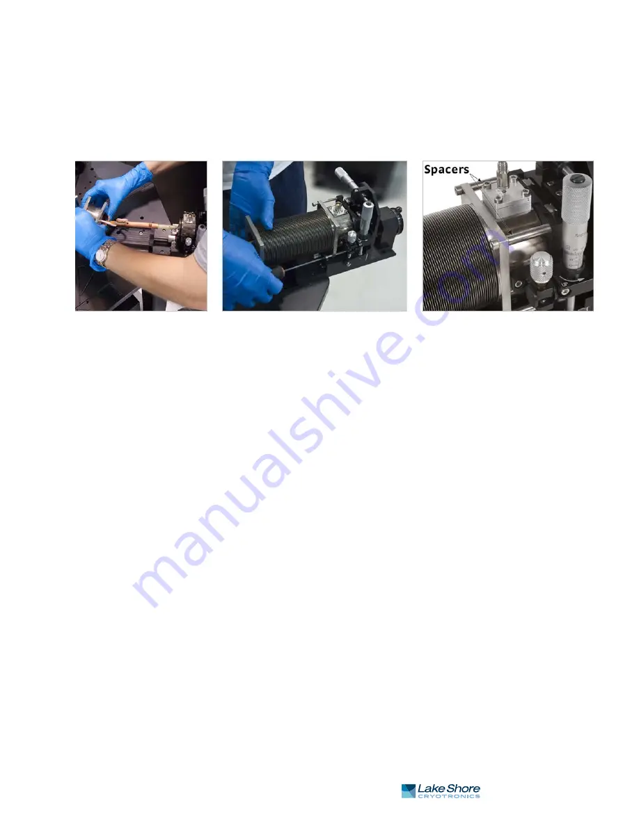
7. Place the bellows over the arm; grasp the square end and carefully twist it down
until the flange meets the probe arm base (FIGURE 5-16).
8. Install the four long M4 horizontal screws that attach the bellows to the z-axis
stage assembly, with the spacers between the bellows and the z-axis stage
(FIGURE 5-16).
9. Tighten the bottom two screws first, and then tighten the top two screws.
5.3.5 Reconfiguring
Ultra-miniature
Cryogenic Coaxial
Cables
If you will be changing cables frequently, it is recommended to have a probe arm and
base available with the appropriate cable already installed, then switch probe arms
using the instructions in section 5.3.3 and section 5.3.4. However, if a reconfiguration
of the ultra-miniature coaxial cable is necessary, follow this procedure to do so.
5.3.5.1 Removing an Ultra-miniature Cryogenic Coaxial Cable
Ultra-miniature coaxial cables are used with ZN50 probes. Use the following steps to
remove an ultra-miniature coaxial cable from a probe arm assembly.
1. Remove the micro-manipulated stage using the instructions in section 5.3.2.
2. Remove the probe arm and base using the instructions in section 5.3.3.
3. Using a 2.5 mm hex driver, remove the four M3 screws that attach the cable feed-
through assembly to the probe arm base (FIGURE 5-17).
4. Remove any ties or tape securing the coaxial cable to the probe arm.
5. Lift the cable feedthrough assembly from the probe arm base.
5.3.5.2 Installing an Ultra-miniature Cryogenic Coaxial Cable
Ultra-miniature coaxial cables are used with ZN50 probes. Follow this procedure to
install an ultra-miniature coaxial cable onto a probe arm assembly. This procedure
assumes that the miniature coaxial cable is already soldered to the connector
feedthrough.
1. Clean the o-ring groove of the signal connector feedthrough in the probe arm
base. Clean, inspect and lightly grease the o-ring with vacuum grease and place it
in the groove.
2. Handling the coaxial cable carefully, insert the SMA end of the coaxial cable into
the hole in the probe arm base (FIGURE 5-17, left). Pull the cable through until
the feedthrough seats on the o-ring in the probe arm base.
3. Using a 2.5 mm hex driver, attach the cable feedthrough assembly to the probe
arm base with four M3 screws (FIGURE 5-17, middle).
4. Wrap the coaxial cable around the probe arm shaft to take up excess length of the
coaxial cable (FIGURE 5-17, right).
FIGURE 5-16
Left: Placing the bellows onto the probe arm base; Middle: Attach the bellows to the z-axis stage;
Right: Spacers between the bellows and the z-axis stage


