116
CHAPTER 5:
Advanced Operation
Model CRX-6.5K Probe Station
5.3.4 Installing a Probe
Arm and Base
If the probe arm base has not been removed from the stage, remove it using the
instructions in section 5.3.3. Then follow this procedure to install a
probe arm assembly.
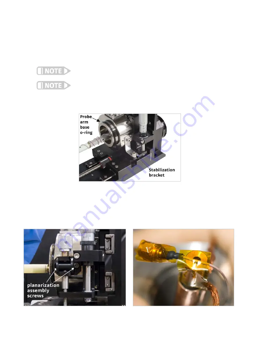
1. Insert the probe arm base into the z-axis stage. Orient the probe arm base as
shown in FIGURE 5-14, and hold it in place. Precise alignment is not necessary.
2. Insert the two threaded dowels into the z-axis stage (FIGURE 5-13).
Tighten until snug.
Access to the threaded dowels may be to the side of the z-axis stage as shown in
FIGURE 5-13 or to the top of the z-axis stage.
The probe arm base is loosely captured by the dowels. It is free to rotate even when you
secure the dowels.
3. If you do not have a planarization assembly, using a 3 mm hex driver, tighten the
M4 screw to secure the stabilization bracket to the probe arm base
(FIGURE 5-14).
4. If you have a planarization assembly, using a 2.5 mm hex driver, tighten the two
M3 screws to secure it to the probe arm base (FIGURE 5-15).
5. If the probe arm has a flexible cable, use a non-residue tape like Kapton® to tem-
porarily tape the cable to the probe arm to easily pull the cable through the
bellows. Place the tape near the end of the cable so it can be removed after the
assembly is installed (FIGURE 5-15).
FIGURE 5-14
Orientation of the probe arm base in the z-axis stage
and location of the stabilization bracket
FIGURE 5-15
Left: Securing the planarization assembly to the probe arm base; Right: Taping the cable to the probe arm


