XII
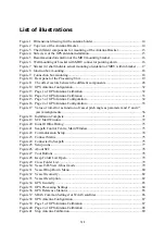
Figure 42 Page 3 of GPS Antenna Configuration .................................................................. 89
Figure 43 Edit Calibration Data ............................................................................................. 90
Figure 44 Page 4 of GPS Antenna Configuration .................................................................. 91
Figure 45 GPS Attitude Processing ........................................................................................ 91
Figure 46 MRU Geometry ..................................................................................................... 92
Figure 47 Step 1 of MRU Axis Orientation ........................................................................... 93
Figure 48 Step 2 of Manual MRU Axis Orientation .............................................................. 93
Figure 49 Step 3 of Manual MRU Axis Orientation .............................................................. 94
Figure 50 Positive offset angles rotations .............................................................................. 95
Figure 51 Step 2 of Auto MRU Axis Orientation .................................................................. 95
Figure 52 Step 3 of Auto MRU Axis Orientation .................................................................. 96
Figure 53 MRU Heave Filter ................................................................................................. 98
Figure 54 Measurement Points Geometry .............................................................................. 99
Figure 55 Common Host Settings ........................................................................................ 100
Figure 56 Common Network Settings .................................................................................. 101
Figure 57 Data Interface - Input Configuration ................................................................... 101
Figure 58 Serial Port Setting ................................................................................................ 102
Figure 59 Format Setting...................................................................................................... 102
Figure 60 RTCM Format Decoding ..................................................................................... 103
Figure 61 Formats available for device type Gyro ............................................................... 103
Figure 62 Data Interface - Output Configuration ................................................................. 104
Figure 63 Network Settings ................................................................................................. 104
Figure 64 Analog Settings .................................................................................................... 105
Figure 65 Measurement Point .............................................................................................. 105
Figure 66 Message Interval Settings .................................................................................... 105
Figure 67 Selection of NMEA output standard .................................................................... 106
Figure 68 Format Settings .................................................................................................... 106
Figure 69 Analog Format Settings ....................................................................................... 107
Figure 70 Datawell Hippy compatible analog output signals .............................................. 107
Figure 71 Input of test voltage for the selected analog channel ........................................... 108
Figure 72 Download Parameters .......................................................................................... 108
Figure 73 Upload Parameters ............................................................................................... 109
Figure 74 Save on file .......................................................................................................... 109
Figure 75 Load from file ...................................................................................................... 110
Figure 76 Undo ..................................................................................................................... 110
Figure 77 Generate configuration report .............................................................................. 111
Figure 78 Configuration report ............................................................................................ 111
Summary of Contents for Seatex Seapath 200
Page 1: ...Seatex Seapath 200 Installation Manual Issued 2008 06 09 ...
Page 2: ...Blank page ...
Page 4: ...IV Blank page ...
Page 6: ...VI Blank page ...
Page 10: ...X Blank page ...
Page 14: ...XIV Blank page ...
Page 18: ...Seatex Seapath 200 Installation Manual rev 13 Introduction 4 Blank page ...
Page 22: ...Seatex Seapath 200 Installation Manual rev 13 Specifications 8 Blank page ...
Page 53: ...Seatex Seapath 200 Installation Manual rev 13 Installation drawings 39 ...
Page 54: ...Seatex Seapath 200 Installation Manual rev 13 Installation drawings 40 ...
Page 55: ...Seatex Seapath 200 Installation Manual rev 13 Installation drawings 41 ...
Page 56: ...Seatex Seapath 200 Installation Manual rev 13 Installation drawings 42 ...
Page 64: ...Seatex Seapath 200 Installation Manual rev 13 Appendix A Installation worksheet 50 Blank page ...
Page 80: ...Seatex Seapath 200 Installation Manual rev 13 Appendix C Installation of coax connectors 66 ...
Page 81: ...Seatex Seapath 200 Installation Manual rev 13 Appendix C Installation of coax connectors 67 ...
Page 82: ...Seatex Seapath 200 Installation Manual rev 13 Appendix C Installation of coax connectors 68 ...
Page 83: ...Seatex Seapath 200 Installation Manual rev 13 Appendix C Installation of coax connectors 69 ...


