background image

Seatex Seapath 200 Installation Manual, rev. 13 


Introduction 

1.3.2


Abbreviations and acronyms 

b-frame 

Body frame. An orthogonal frame fixed to the MRU housing or to the 
vehicle where the MRU is fixed. 

CEP 

Circular Error Probability. 

CG 

Centre of gravity. The mass centre of a vessel. This is normally the location 
with least linear acceleration, and hence the best location for measurements 
of roll and pitch. 

EMI 

Electromagnetic interference. 

g-frame 

Geographic frame. An orthogonal frame having axes pointing North, East, 
and Down at the current location of the vehicle. 

GPS Time 

The time in the GPS system. The GPS time is within UTC time 

±

180 nsec 

(95 per cent) plus leap seconds. 

IMU 

Inertial Measurement Unit. A system consisting of gyros and 
accelerometers. 

LGND 

Logic Ground. 

MP 

Measurement Point. 

MRU 5 

Motion Reference Unit, model 5. This is the IMU within the Seapath 
measuring dynamic linear motion and attitude. 

NMEA 

National Marine Electronics Association. NMEA 0183 is a standard for 
interchange of information between navigation equipment. 

P-axis 

This axis is fixed in the vehicle, and points in the starboard direction 
horizontally when the roll angle is zero. Positive rotation about this axis is 
bow of the vehicle up. 

PGND 

Power Ground. 

PPM 

Parts per million. 

1PPS 

One Pulse Per Second. 

RFI 

Radio Frequency Interference. 

RMS 

Root Mean Square. 

R-axis 

This axis is fixed in the vehicle, and points in the forward direction 
horizontally when the pitch angle is zero. Positive rotation about this axis is 
starboard side of the vehicle down. 

SBAS 

Satellite Based Augmentation System 

SCC 

Seapath Control Centre is special software used to set configuration 
parameters in Seapath. The software runs under Microsoft Windows version 
95, 98, NT 4.0 or compatible on a PC. 

UTC 

Universal Time Co-ordinated. This is the official time in the world and has 
replaced GMT (Greenwich Mean Time) as the official time.  

Y-axis 

This axis is fixed in the vehicle and points in the downward direction when 
the vehicle is aligned horizontally. Positive rotation about this axis is 
turning the bow of the vehicle to starboard. 


Summary of Contents for Seatex Seapath 200

Page 1: ...Seatex Seapath 200 Installation Manual Issued 2008 06 09 ...

Page 2: ...Blank page ...

Page 3: ... this manual However should any errors be detected Kongsberg Seatex AS would greatly appreciate being informed of them The above notwithstanding Kongsberg Seatex AS can assume no responsibility for any errors in this manual or their consequences Copyright 2008 by Kongsberg Seatex AS All rights reserved Kongsberg Seatex AS Pirsenteret N 7462 Trondheim Norway Telephone 47 73 54 55 00 Facsimile 47 73...

Page 4: ...IV Blank page ...

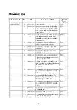
Page 5: ...h version 2 0 software FOS 6 2000 11 22 Updated to correspond with latest version of the Processing Unit with analog output channels FOS 7 2000 12 18 Corrected polarity for the RS 422 DB 9 connector updated Installation Worksheet with RS232 422 selection FOS 8 2003 02 12 Updated to correspond with Seapath sw version 2 02 and SCC version 2 1 FOS 9 2003 06 10 Updated with the possibility to disable ...

Page 6: ...VI Blank page ...

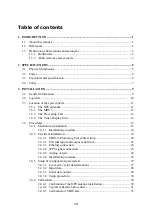
Page 7: ...Display Unit 13 3 4 Procedures 13 3 4 1 Mechanical installation 13 3 4 1 1 Installation procedure 14 3 4 2 Electrical installation 19 3 4 2 1 MRU to Processing Unit cable wiring 20 3 4 2 2 External input and output serial lines 21 3 4 2 3 Ethernet connection 23 3 4 2 4 1PPS signal connection 23 3 4 2 5 Analog output 24 3 4 2 6 Installation procedure 25 3 4 3 Setup of configuration parameters 27 3 ...

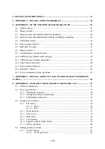
Page 8: ...nsweep format 60 6 13 Echo sounder format 18 61 6 14 Submetrix format 61 6 15 Cyclic redundancy check algorithm 63 7 APPENDIX C INSTALLATION OF COAX CONNECTORS ON SUPERFLEX CABLE 65 8 APPENDIX D SEAPATH CONFIGURATION SOFTWARE SCC 71 8 1 Software installation 71 8 2 How to get started 72 8 2 1 Starting the program 72 8 2 2 Setting the serial port parameters 74 8 2 3 Establishing connection 74 8 3 G...

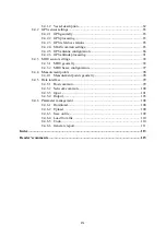
Page 9: ...RU sensor settings 92 8 4 3 1 MRU geometry 92 8 4 3 2 MRU heave configuration 97 8 4 4 Measurement points 98 8 4 4 1 Measurement points geometry 98 8 4 5 Data interface 99 8 4 5 1 Host common 99 8 4 5 2 Network common 100 8 4 5 3 Input 101 8 4 5 4 Output 103 8 4 6 Parameter management 108 8 4 6 1 Download 108 8 4 6 2 Upload 109 8 4 6 3 Save on file 109 8 4 6 4 Load from file 110 8 4 6 5 Undo 110 8...

Page 10: ...X Blank page ...

Page 11: ... Configuration 34 Figure 16 Page 4 of GPS Antenna Configuration 35 Figure 17 Value of roll error as function of vessel pitch angle as parameter and 1 and 2 yaw misalignments 36 Figure 18 Installation Complete 71 Figure 19 SCC Start Window 72 Figure 20 Initial Offline Dialog 73 Figure 21 Seapath Control Centre Main Window 73 Figure 22 Communication Setup 74 Figure 23 Connect Status 75 Figure 24 Con...

Page 12: ... 57 Data Interface Input Configuration 101 Figure 58 Serial Port Setting 102 Figure 59 Format Setting 102 Figure 60 RTCM Format Decoding 103 Figure 61 Formats available for device type Gyro 103 Figure 62 Data Interface Output Configuration 104 Figure 63 Network Settings 104 Figure 64 Analog Settings 105 Figure 65 Measurement Point 105 Figure 66 Message Interval Settings 105 Figure 67 Selection of ...

Page 13: ... 1 38120 md 007 Seapath 200 Antenna Holder 4 1 hs 003 a MRU housing External dimension 4 1 hs 016 b MRU M MB3 bracket Hydrographic version 1 1 hs 014 a MRU junction box MRU E JB1 Layout and ext dimensions 1 1 M410 32 Processing Unit Connection Box 0 1 M320 42 Cable Processing Unit Aux Serial Analog Output 0 1 ...

Page 14: ...XIV Blank page ...

Page 15: ...ntation of the Installation Manual with references and abbreviations Chapter 2 Specifications Describes the physical dimensions required power environmental and cable specifications Chapter 3 Installation Presents procedures to be followed for a typical ship installation with recommendations on location of the different parts mechanical and electrical installation and how to set up and calibrate t...

Page 16: ...he direction of the main axis bow direction of the vehicle as opposed to course which is the direction of motion of the vehicle Yaw angle as defined here is the same as heading heave The vertical dynamic motion of a vehicle and defined positive down Heave position and velocity are dynamic motion variables with a certain lower cutoff frequency host system In this manual defined as Navigation comput...

Page 17: ...sociation NMEA 0183 is a standard for interchange of information between navigation equipment P axis This axis is fixed in the vehicle and points in the starboard direction horizontally when the roll angle is zero Positive rotation about this axis is bow of the vehicle up PGND Power Ground PPM Parts per million 1PPS One Pulse Per Second RFI Radio Frequency Interference RMS Root Mean Square R axis ...

Page 18: ...Seatex Seapath 200 Installation Manual rev 13 Introduction 4 Blank page ...

Page 19: ...14 mm Width 89 mm Height 55 mm Weight 0 3 kg Colour Grey Video Display Unit 17 LCD Samsung SyncMaster 710n Width 380 mm Height 383 mm Depth 170 mm Weight 3 8 kg Colour Black Silver MRU 5 Height 204 mm Diameter 105 mm Weight 2 5 kg Colour Blue MRU Mounting Bracket MRU M MB3 Length 265 mm Width 119 mm Height 119 mm Weight 1 6 kg Colour Black Material POM H MRU Junction Box MRU E JB1 Length 226 mm Wi...

Page 20: ...t Enclosure material Aluminium Enclosure protection IP 30 Operating temperature range 0 to 55ºC Operating humidity 20 to 80 relative Storage temperature range 20 to 60ºC Storage humidity Less than 55 Vibration testing according to EN 60945 Connection Box M410 32 Material Aluminium Enclosure protection IP 20 Video Display Unit 17 LCD Samsung SyncMaster 710n Operating temperature range 5 to 40ºC Rel...

Page 21: ...max 100 2 4 Cable Cable MRU E CS1 Type Heavy Duty Screened Habia Aquatherm RTFR 14x2x0 25 mm2 Length 3 m Diameter 13 5 mm Flame retardation IEC 332 1 Insulation ETFE Screen Cu braid Processing Unit to MRU Junction Box Cable Type LAMAC 4x2x0 5 mm2 Maximum length 100 m Diameter 10 mm Flame retardation IEC 332 3 A The GPS Antenna Cables Coax Type NK Superflex 50 BHF Attenuation 14 dB 100 m at 1 6 GHz...

Page 22: ...Seatex Seapath 200 Installation Manual rev 13 Specifications 8 Blank page ...

Page 23: ... is supplied with the following parts The Processing Unit The Processing Unit connection box with 1 5 metre cable Video Display Unit and standard keyboard The MRU 5 unit The MRU mounting bracket MRU M MB3 Junction box MRU E JB1 with three metres MRU E CS1 cable Two GPS antennas A 2 5 metre aluminium Antenna Bracket Setup software power cable a null modem configuration cable and documentation ...

Page 24: ...cided and the necessary cables and connectors made available Power supply for the Processing Unit and an external computer for setup and calibration are also needed An external heading reference for example a surveyed quay is required for heading calibration For some applications pitch and roll reference for calibration is also needed The MRU unit is shipped in a specially designed transportation ...

Page 25: ...a This since Seapath also utilises carrier phase measurements for heading determination and both GPS antennas need to see at least two common satellites at the same time The GPS antennas have to be mounted in a way that avoids blocking of the GPS signal In order to reduce problems due to multipath effects the GPS antennas have to be mounted above the nearest deck at a height which is equal to the ...

Page 26: ...sure motion of a particular user equipment mount the MRU as close to the ship s centre of gravity CG as possible This to ensure best roll and pitch measurements If it is not possible to mount the MRU close to CG try to mount it along the longitudinal axis of the ship and as close to the CG as possible Avoid mounting the MRU high up or out to the side of the ship Be aware of Vibrations Direct mount...

Page 27: ...des of the unit All connections to the unit are on the rear side and available space for cable connections and service must be provided 3 3 4 The Video Display Unit For location of the table mounted Video Display Unit consider the following The unit is designed for installation in an indoor environment and for operation within the temperature range The best location is typically on a table in the ...

Page 28: ... two GPS antennas and the antenna cables as close as possible to the location of the antenna holder While both the GPS antennas and the Antenna Bracket are down on deck mount the GPS antennas on the Bracket with both antennas oriented in the same direction Depending on antenna type labelling on the antenna housing arrow or text or connector location is used to determine direction Figure 2 shows th...

Page 29: ...3 The different components for mounting of the Antenna Bracket Ensure that the delivered insulation plate is used between the Antenna Bracket and the holder and that the four bushings are placed in the mounting holes before the screws are entered The nuts should be secured with washers or by utilising self locking nuts Figure 4 Side view of the GPS antenna installation 5 When the best mounting loc...

Page 30: ...ure 5 Recommended orientation of the MRU mounting bracket 6 Mount the MRU bracket on the wall preferably with the opening pointing down as shown in Figure 6 Mark and drill a M6 hole for the top screw 1 and enter the screw without tightening it completely Align the bracket vertically using its own weight or by aligning it in relation to the wall Drill two holes for the lower screws 2 and insert and...

Page 31: ... exchanged or removed temporarily Figure 7 Sticker 4 shall indicate actual mounting orientation of MRU within bracket Note If the MRU is mounted correctly in the bracket the R arrow on the top of the MRU will point in the bow direction of the ship and the same direction as the R axis of the sticker If uncertain whether the MRU R axis is pointing in the bow direction look under the MRU and check th...

Page 32: ... both in front and rear of the rack Minimum 10 cm free space is needed behind the module for connecting cables 11 Mount the connection box part no M410 32 on a suitable location within the length of its 1 5 metre cable to the 15 pin MRU port on the Processing Unit as shown in Figure 9 The two screws for mounting the connection box should be secured with washers or self locking nuts Figure 9 Connec...

Page 33: ...ections to the Processing Unit optional Connecting a cable with data output on the Ethernet between the Ethernet connector at the rear of the Processing Unit and external equipment optional Connecting a cable with 1PPS output signal between the between the PPS connector at the rear of the Processing Unit and external equipment optional GPS 1 GPS 2 IALA NET USB NET MOUSE KEYB VGA PPS AUX Serial LPT...

Page 34: ...1 side T 3 RX 3 white 5 x1 side S 10 RX 3 blue 6 x1 side P 11 XIN 4 white 23 x1 side U 5 LGND 4 blue 24 x1 side a For the last alternative with termination in the MRU junction box in one end and termination in the Processing Unit connection box in the other end the cable wiring is as follows Processing Unit Signal Pair no PU connection box MRU junct box Pin no Colour Pin no Pin no 1 screen 9 chass...

Page 35: ...r output default output data to host com6 RS 232 or 422 default 232 User configurable input or output default output data to host com7 RS 232 or 422 default 232 User configurable input or output default output data to host com8 RS 232 or 422 default 232 User configurable input or output default output data to host com9 RS 232 or 422 default 232 User configurable input or output default gyro compas...

Page 36: ... six comports are available These ports are default RS 232 serial lines The pin layout is described below Pin no Signal Line Description 1 GND 14 RX Com4 RS 232 not galvanically isolated 2 TX 15 GND 3 RX Com14 RS 232 not galvanically isolated 16 TX 18 GND 6 RX Com15 RS 232 not galvanically isolated 19 TX 7 GND 20 RX Com16 RS 232 not galvanically isolated 8 TX 21 GND 9 RX Com17 RS 232 not galvanica...

Page 37: ...owever shielded is recommended used The maximum length of the cable that can be used is 100 metres 328 ft A straight through cable is one where the pins of one connector are connected to the same pins of the other connector In special instances a crossover cable instead of straight through is needed like connecting a Seapath Processing Unit and an HMS 100 Computing Unit together Below is the pin w...

Page 38: ...ariable and channel properties is performed in the SCC configuration software see chapter 8 4 5 4 for details The pin wiring for the analog output part of the AUX Serial port is as follows AUX Serial port Pin no Signal Description 24 AGND Common ground for all analog signals 12 AOUT 1 Analog output signal for channel no 1 25 AOUT 2 Analog output signal for channel no 2 13 AOUT 3 Analog output sign...

Page 39: ... before the cable is fastened to the box Use the required number of clips to fasten the cable to the wall Insert each of the MRU to Processing Unit cable wires into the correct terminal on the user side x1 and all cable shields to pin 1 chassis on the auxiliary contact side x3 within the box Ensure that the shield around each pair is individually isolated in the DB 15 connector in the other end an...

Page 40: ...t and the keyboard to the corresponding connectors at the rear of the Processing Unit 6 Connect the Video Display Unit to 110 230V AC ship s power 7 If available connect the cables with the DGPS corrections to port com10 and the external gyro compass signal to com9 at the rear of the Processing Unit Optionally additional DGPS correction signals can be connected to the free communication ports in t...

Page 41: ...or the actual installation will be easier to find when requested later 3 4 3 1 Lever arm vector determinations The following lever arm vectors have to be determined and input to the configuration software SCC The vector from the centre of gravity to the GPS antenna no 1 The vector from the centre of gravity to the MRU location The vectors from the centre of gravity with up to maximum four measurem...

Page 42: ...ionally the additional input lines on the AUX Serial port can be used Heading data from an external source for example a gyro compass as backup to improve reliability Heading is normally input through the port com9 The data format must conform to an 1 HDT message or a supported proprietary format If DGPS correction data from more than one reference station are available on the links Seapath combin...

Page 43: ... 0 1 second between messages the lowest channel numbers should be used for the highest data rates The points on the vessel where the output positions and velocities shall be valid measurement points must be defined If points different from centre of gravity shall be used the offsets from centre of gravity to these points have to be specified in the Measurement Points Geometry window in SCC A maxim...

Page 44: ...ype of reference must be decided according to the required accuracy Calibrate the MRU axes measured by the MRU against an external reference Decision on whether MRU calibration is needed and type of reference is based on the type of system the Seapath is interfaced to and the accuracy required 3 4 4 1 Calibration of the GPS antenna installation For the GPS antenna installation the following calibr...

Page 45: ...the calibration value should be added to the existing offset value The baseline length and height difference should be determined within an accuracy of 10 centimetres in height difference and 1 mm in baseline length These values should be entered into the Seapath through the SCC software By using the calibration wizard in the SCC software the baseline length and height difference are calculated au...

Page 46: ...1 cm accuracy and this value entered For the Heading Offset input an approximate value or input zero if you are uncertain For the Height Difference input an approximate value Then click on the Calibration Wizard button to prepare the calibration Figure 12 GPS Antenna Configuration 4 In the GPS Antenna Calibration Wizard Page 1 step 1 check that the baseline length has been entered correctly Figure...

Page 47: ...art recording data of the vessel reference heading on another PC or by manual readings When logging of the reference heading has started click Next in order to proceed to page 2 7 The progress of the calibration process is then shown on the screen with a graphical presentation of the measured data for the Seapath heading the gyro compass if connected the antenna baseline length and the height diff...

Page 48: ...command Show Graph Correct the wild points found or delete the whole line s and perform a recalculation of the calibration data 10 When the Seapath calibration result has been found acceptable click Next to proceed to page 4 Input the mean value for the vessel heading reference in this example logged on a separate PC and found to be 7 83 degrees and click on Compute in order to calculate the headi...

Page 49: ...the specified roll and pitch accuracy the offset angles between the MRU axes and the vessel axes have to be calculated to an accuracy better than 0 5 degrees These offset angles are input to the Seapath configuration as mounting angles For multibeam echo sounder applications an accuracy better than 0 1 degrees is required to ensure satisfactory performance A typical calibration consists of calibra...

Page 50: ...of crucial importance If not properly aligned the performance of the roll and pitch measurements from MRU will be degraded The easiest way to ensure a correct yaw orientation of the MRU is to mount the unit on the vessel s longitudinal or transversal bulkheads Figure 17 illustrates that a misalignment of 1 degree of the MRU in yaw will result in a roll error of 0 09 degrees if the vessel is pitchi...

Page 51: ...3 Installation drawings 37 4 INSTALLATION DRAWINGS This chapter contains the outline drawings showing the mechanical dimensions of the Processing Unit the GPS Antenna Bracket and Holder the MRU 5 and its mounting bracket and the MRU junction box ...

Page 52: ...jection Rev Description Date Date Sign Design by Usage Rev no Scale 31438 MA 010 HW PLATTFORM 1 5 KL 99 05 03 04 11 25 4 Standard enclosure for mounting in 19 racks Basic material Aluminium Fits into slots with height 3 Units 1U 44 45mm ENCLOSURE DIMENSIONS KONGSBERG SEATEX Assey 443 430 33 6 465 57 1 132 5 3U 482 DETAIL A 3 5 R 3 5 A ...

Page 53: ...Seatex Seapath 200 Installation Manual rev 13 Installation drawings 39 ...

Page 54: ...Seatex Seapath 200 Installation Manual rev 13 Installation drawings 40 ...

Page 55: ...Seatex Seapath 200 Installation Manual rev 13 Installation drawings 41 ...

Page 56: ...Seatex Seapath 200 Installation Manual rev 13 Installation drawings 42 ...

Page 57: ... pair Cable Item Quant Description A1 B1 G1 G2 1 ea 1 ea 1 ea 1 ea X1 W1 1 ea 1 ea JB1 1 ea D sub connector 15 pin male Diecast housing for D sub connector Cable Gland Type Skintop MS SC 11w backnut Miltronic Art nr 120109 Terminal list Type Phoenix MBK 3 Art nr 1413010 Marking Art nr 1401802 0001 Junction Box Type ELFA Art nr 50 025 30 Signal cable 4 pair x 0 22mm2 1 5 m Cable Gland Type Skintop ...

Page 58: ...l Page P Kjellstrøm 1 of 1 Visio 5 0 0 Kongsberg Seatex AS Traced P Kjellstrøm Sign Scale Sign Sign Date Last revision date 2004 01 20 W1 P1 P2 1 1 2 3 4 B1 Item Quant Description A1 B1 W1 1 ea 1 ea 1 ea D sub connector 25 pin female Diecast housing for D sub connector Signal cable 2 pair x 0 22mm2 3 m RFE HF 2x2x0 5mm2 Codes P1 Pair no 1 P2 Pair no 2 A1 24 25 12 13 SCR P2 P1 1 2 3 4 AGND AOUT 2 A...

Page 59: ...f Gravity CG Location From CG to AP Aft Point m positive forward of CG From CG to CL Centre Line m positive to starboard of CG From CG to the Keel m positive below CG Vessel Description Vessel Data Vessel Type and Name Vessel Owner Country of Origin Management Manager Phone Number Seapath Seapath Owner Seapath Manager GPS Antenna Geometry Antenna Lever Arm from CG to Antenna 1 X m positive forward...

Page 60: ...eference Stations Only Stations Force Stations Ignore Stations SBAS Common Settings SBAS Enable Automatic mode default disabled GEO SV s to track SBAS Decode Decode any satellite default disabled Decode following SVs Enable SBAS WASS Testmode default disabled GPS Antenna Configuration Baseline length standard 2 500 m Heading offset Reference Seapath reading deg Height difference standard 0 00 m GP...

Page 61: ... Mode Average period s Damping Measurement Points 0 4 CG not counted Offset from CG to each measurement point Point no Active X positive if MP forward of CG m Y positive if MP starboard of CG m Z positive if MP below CG m Name of MP 1 2 3 4 Data Interface Common Host Settings NMEA Identification 2 characters Binary Message Token 0 255 Data Interface Common Network Settings IP Network Address IP Ne...

Page 62: ...andard n Data bits st 8 Stop bits st 1 Format Gyro DGPS Link 1 DGPS Link 2 DGPS Link 3 DGPS Link 4 OpCom default Com1 Data Interface Digital RS 232 422 Output Configuration Device Line com Electric 232 422 Baud rate Parity st n Data bits st 8 Stop bits st 1 MP 0 CG Int s Op 0 Format Host Out 1 Host Out 2 Host Out 3 Host Out 4 Host Out 5 Host Out 6 Host Out 7 Host Out 8 ...

Page 63: ...ut Configuration Device Port MP 0 CG Int s Option st 0 Format Network Out 1 Network Out 2 Network Out 3 Network Out 4 Network Out 5 Network Out 6 Network Out 7 Network Out 8 Data Interface Analog Output Configuration Device Gain V Physical Unit Offset Physical Unit MP 0 CG Format Analog Out 0 Analog Out 1 Analog Out 2 ...

Page 64: ...Seatex Seapath 200 Installation Manual rev 13 Appendix A Installation worksheet 50 Blank page ...

Page 65: ...under fmt18 18 Echo sounder format TSS1 compatible Submetrix 19 Submetrix format 6 1 NMEA format The NMEA format is an ASCII text format using the ZDA GGA GLL VTG HDT GST GSA and GRS messages defined in 1 and the proprietary PSXN 20 PSXN 21 PSXN 22 and PSXN 23 messages conforming to the same specification Format INZDA time day month year csum term INGGA time lat N S long E W gga qual nsat hdop hei...

Page 66: ... on format d dd 0 00 359 99 speed Speed over ground knots on format k k head Heading degrees true on format d dd 0 00 359 99 semi maj Standard deviation of the semi major axis of the position error ellipse in metres on format m mm semi min Standard deviation of the semi minor axis of the position error ellipse in metres on format m mm ell orient Orientation of the semi major axis of the position e...

Page 67: ...tween but not including the preceding and hexadecimal 00 FF term CR LF 2 bytes values 13 and 10 The ZDA GGA GLL VTG HDT GST GSA GRS PSXN 20 PSXN 22 and PSXN 23 messages are output regularly at an adjustable rate If gyro calibration data are not being calculated the PSXN 22 message is not output The PSXN 21 message is output once when an event occurs A sub set of the available NMEA messages can be ...

Page 68: ...st significant bit A 1 value true means Bit no Interpretation 0 Reduced horizontal position and velocity performance 1 Invalid horizontal position and velocity data 2 Reduced heave and vertical velocity performance 3 Invalid heave and vertical velocity data 4 Reduced roll and pitch performance 5 Invalid roll and pitch data 6 Reduced heading performance 7 Invalid heading data The remaining bits in ...

Page 69: ...signed 2 byte unsigned and 2 byte two complement integer data elements For the 2 byte elements the least significant byte is transmitted first Format Element Scaling Format Bytes Value Status byte Unsigned 1 Header Unsigned 1 90 Hex Roll 0 01 degrees Integer 2 17999 to 17999 Pitch 0 01 degrees Integer 2 17999 to 17999 Heave 1 cm Integer 2 999 to 999 Heading 0 01 degrees Unsigned 2 0 to 35999 Roll ...

Page 70: ...s true heading from the GPS phase measurement which is not the same as the heading output on the other formats Gyro heading is from an external gyro 0 00 if no gyro is connected Baseline is the slant range between the antenna centres from the GPS phase measurement Height is the height difference between the antennas from the GPS phase measurement Height is positive if antenna 1 is above antenna 2 ...

Page 71: ...nt Format PRDID pitch roll head term Explanation pitch Pitch degrees on format sddd dd s is the sign character or ddd dd is a decimal number with leading zeroes where appropriate Positive with bow up roll Roll degrees on format sddd dd s is the sign character or ddd dd is a decimal number with leading zeroes where appropriate Positive with port side up head Heading degrees true on format ddd dd wi...

Page 72: ...orithm is described in a separate section Time is divided in an integer seconds part and a fractional second part The integer seconds part of time is counted from 1970 01 01 UTC time ignoring leap seconds Latitude is positive north of the Equator Longitude is positive east of Greenwich Height is above the ellipsoid Heave is positive down Roll is positive with port side up Pitch is positive with bo...

Page 73: ...t The next time pulse appears at the first integer second after the time in the message Format INZDA time day month year csum term Explanation time UTC time on format hhmmss ss where hh is hours 00 23 mm is minutes 00 59 and ss ss is seconds 00 00 59 99 day Day of month 01 31 month Month of year 01 12 year Year on format yyyy csum Checksum exclusive or of all characters between but not including t...

Page 74: ...ces 6 12 Atlas Fansweep format The Atlas format is a proprietary binary format used for outputting data to Atlas Fansweep echo sounders It consists of a fixed length message using single byte and 2 byte two complement integer data elements For the 2 byte elements most significant byte is transmitted first Format Element Scaling Format Bytes Value Start byte Integer 1 10 Hex Roll 214 90 degrees Int...

Page 75: ... used for acceleration when this format is output from other systems Seapath does not output acceleration s is the sign character space if positive and if negative dddd is a decimal number with leading zeroes where appropriate The warning character is F if data are normal f if data are invalid or of reduced quality Columns between elements are filled with spaces The definition of the attitude angl...

Page 76: ...such that the minimum value is output as 0 and the maximum value is output as 65535 FFFF Hex Roll is positive with port side up Pitch is positive with bow up Heave and vertical velocity are positive down The start byte is ASCII Unused elements are output as 0 The checksum byte is calculated as a sum modulo 256 of all bytes transmitted excluding the checksum byte The status byte indicates the heave...

Page 77: ...rtran source code below C code define POLY 0x8408 unsigned short blkcrc unsigned char bufptr message buffer unsigned long len number of bytes unsigned char i unsigned short data unsigned short crc 0xffff if len 0L return crc do for i 0 data unsigned short 0xff bufptr i 8 i data 1 if crc 0x0001 data 0x0001 crc crc 1 POLY else crc 1 while len crc crc data crc crc crc 8 data 8 0xff return crc Fortran...

Page 78: ...EQ 0 THEN crc 0 RETURN END IF DO i 1 len data ICHAR inbuffer i i DO bit 1 8 data IAND data 16 FF IF IAND crc 16 01 EQ IAND data 16 01 THEN crc ISHL crc 1 ELSE crc ISHL crc 1 crc IEOR crc poly END IF data ISHL data 1 END DO END DO data IEOR crc 16 FFFF crc IOR ISHL data 8 IAND ISHL data 8 16 FF END ...

Page 79: ...C Installation of coax connectors 65 7 APPENDIX C INSTALLATION OF COAX CONNECTORS ON SUPERFLEX CABLE This is the assembly instruction for the Huber Suhner connectors 11 716 50 9 9 11 N 50 9 9 21 716 50 9 9 and 21 N 50 9 9 This connector consists of one part ...

Page 80: ...Seatex Seapath 200 Installation Manual rev 13 Appendix C Installation of coax connectors 66 ...

Page 81: ...Seatex Seapath 200 Installation Manual rev 13 Appendix C Installation of coax connectors 67 ...

Page 82: ...Seatex Seapath 200 Installation Manual rev 13 Appendix C Installation of coax connectors 68 ...

Page 83: ...Seatex Seapath 200 Installation Manual rev 13 Appendix C Installation of coax connectors 69 ...


Page 84: ...Seatex Seapath 200 Installation Manual rev 13 Appendix C Installation of coax connectors 70 Blank page ...

Page 85: ...h Seapath through a serial line 8 1 Software installation Follow the procedure below to install the SCC software on the external PC 1 Insert SCC CD ROM into the CD or DVD drive on the local PC 2 From the Start menu select Settings Then select Control Panel and Install program Follow the instructions on the screen in order to complete the installation of the SCCSetup exe program 3 When the installa...

Page 86: ...em cable is delivered with Seapath Start Microsoft Windows Start SCC by double clicking on the SCC icon The Seapath SCC start window shows the software version and a rotating Kongsberg Seatex AS logo indicates a running application To continue click one of three buttons 1 Connect System tries to establish communication with Seapath If connection fails Figure 23 is shown 2 Offline System opens for ...

Page 87: ...ck OK Figure 20 Initial Offline Dialog If option Open existing Seapath parameter file is selected the window Select file to load parameters from appears Select the parameter file to be edited and click Open The main window Seapath Control Centre appears see Figure 21 This main window also appears if the option Create a Seapath demo parameter file is chosen Figure 21 Seapath Control Centre Main Win...

Page 88: ...re saved and will remain unchanged until reconfigured Figure 22 Communication Setup 8 2 3 Establishing connection Click the Connect to Seapath button or pull down the File menu and select the SCC to Seapath Communication Connect The Connect to Seapath Status window becomes active if communication is OK Figure 24 is shown If the Seapath type and version is correct accept by clicking OK If the conne...

Page 89: ... D Seapath configuration software SCC 75 Figure 23 Connect Status Figure 24 Connected to Seapath Note Before editing parameter values belonging to a connected Seapath it is recommended to perform an Upload from the Seapath first See chapter 8 4 6 2 Upload ...

Page 90: ...Port Configuration See chapter 8 2 2 Setting the serial port parameters Demo See chapter 8 3 1 1 Print Configuration Self explanatory Print Preview Self explanatory Print Setup Self explanatory Recent File Self explanatory Exit See chapter 8 3 1 2 8 3 1 1 Demo Click on the Demo option and the system enters parameter examples into the different settings making it possible to play with the applicati...

Page 91: ...on Wizard to activate the GPS Antenna Calibration Wizard window The Calibration settings are described in chapter 8 4 2 5 GPS antenna configuration 8 3 3 View menu Pull down the View menu Tick off to view the wanted options 3 Toolbar See detailed information in chapter 8 3 5 3 Status Bar Bottom line 3 SCC Mode Select Bar See Figure 25 Setup icons 3 Advanced Options For use by service personnel onl...

Page 92: ... Description of tool buttons from left to right Open Configuration Self explanatory Save Configuration Self explanatory Connect to Seapath Establishes data communication from SCC to Seapath Disconnect from Seapath Disconnects data communication between SCC and Seapath SCC Seapath Port Configuration See chapter 8 2 2 Setting the serial port parameters MRU Configuration Wizard See chapter 8 4 3 1 MR...

Page 93: ...ner of the folder list to place this folder on the left side of the configuration folder To remove the folder list and return to the original main window click the X button in the upper right corner Figure 29 Close Folder List Click the Vessel 3D View button to show an expanded vessel window The vessel window will cover the whole screen like the figure below here shown in Ghost mode Click the Vess...

Page 94: ... in the upper right vessel window and the mouse arrow changes into a zoom symbol The vessel model can then be zoomed both out and in Press CTRL and simultaneously point and left click with the mouse pointer in the upper right vessel window and the mouse arrow changes into a move symbol The vessel model can then be moved around within the window Point and right click with the mouse pointer in the u...

Page 95: ...asurement Points group contains information on up to maximum four Measurement Points The Data Interface contains in out parameters to be edited when defining communication with external systems The Parameter Management group contains user features for loading and saving Note For this new version of the SCC software the sensor parameters for the MRU are to be set from this software only Note Rememb...

Page 96: ...escription In this folder vessel data for the specific Seapath configuration file are entered This information is helpful to identify the correct configuration file at a later stage Proceed as follows In the Configuration Folder List select Vessel Description Set general vessel data and management information Figure 33 Vessel Description ...

Page 97: ...heck the signs and the co ordinates input for GPS antenna no 1 the vessel dimension and the entered location of CG Figure 34 GPS Geometry 8 4 2 2 GPS processing For operations with weak satellite geometry the position output can be made more accurate by using height aiding and low elevation mask For normal operations the Height Aiding mode is set to Off but Filter is also recommended used The elev...

Page 98: ... Seapath to use the ranges from the Geo stationary satellites in the SBAS system like WAAS EGNOS or MSAS Be aware that the Geos are less accurate than the GPS ranges Geo ranges should not be used without differential corrections such as SBAS The default setting is without use of Geo ranges For the Seapath 200 RTK version the search mode for the RTK solution be changed from the default mode Normal ...

Page 99: ...Age Limit for Differential Corrections Figure 36 GPS Reference Stations For more information whether to override the automatic selections or not see the description in the User s Manual 3 chapter 5 Operating Instructions 8 4 2 4 SBAS common settings The following configuration settings are available for SBAS SBAS Enable The preferred option is to manually select which two or one satellites to trac...

Page 100: ...WAAS Testmode WAAS is operational and the test mode should be disabled Figure 37 SBAS Common Settings for WAAS satellites For more information on how to use SBAS corrections see the description in the User s Manual 3 chapter 5 Operating Instructions 8 4 2 5 GPS antenna configuration The heading of the GPS antenna baseline direction relative to the vessel s heading must be input to the software At ...

Page 101: ...e the Calibration Wizard button and page 1 of the GPS Antenna Calibration appears Enter the baseline and calibration information asked for in step 1 and 2 and click Next in order to proceed to page 2 See chapter 3 4 4 2 Typical calibration procedure for a detailed example of antenna calibration Figure 39 Page 1 of GPS Antenna Calibration ...

Page 102: ...ntation in their respective diagram The diagrams are auto scaled in order to show the total calibration period A progress bar shows the calibration progress Figure 40 Page 2 of GPS Antenna Calibration Click the Back or Cancel button at any time if you want to stop the calibration process see the window in Figure 42 Accept to stop the calibration by clicking Yes or click No to continue Click Next d...

Page 103: ...ontinues to page 3 Figure 42 Page 3 of GPS Antenna Configuration GPS Antenna Calibration page 3 contains information about the calibration measurements result Here it is possible to edit or delete lines of measurements Select a line by pointing on it Click on the Count or Time cell choose to edit or delete the line Click on the Edit line button and the Edit Calibration Data dialogue box appears Th...

Page 104: ...alculate to update the calibration statistics including the changes Only saved changes are included Click Show Graph to see the updated graph Click Next to proceed to page 4 In page 4 the vessel reference heading can be input Click Compute in order to calculate the heading offset Click Finish to accept the result and terminate the calibration Note If there are too many wild points and lines that n...

Page 105: ...figuration software SCC 91 Figure 44 Page 4 of GPS Antenna Configuration 8 4 2 6 GPS attitude processing In the Configuration Folder List select Sensor GPS Attitude Processing Enter the maximum values to be used for attitude processing Figure 45 GPS Attitude Processing ...

Page 106: ... MRU Geometry Enter the settings for MRU Lever Arm Look at the sketch of the MRU geometry on the screen in order to enter correct signs on the co ordinates Check also that the MRU has been located on the expected spot in the vessel window If not check the signs and the co ordinates input for the MRU the vessel dimension and the entered location of CG Figure 46 MRU Geometry The MRU mounting angles ...

Page 107: ...o go to the Step 2 Manual window as shown in Figure 48 Click the Previous or Next buttons in the left part of the window to turn the MRU unit around in 90 degree steps axis by axis Click until the correct mounting orientation of the MRU has been found The right part of the window is automatically updated with the actual main rotation of the MRU Figure 48 Step 2 of Manual MRU Axis Orientation ...

Page 108: ...ain rotation angles A positive offset angle rotation is Positive roll offset means starboard right side facing downward or a clockwise rotation about the R axis Positive pitch offset means bow up or a clockwise rotation about the P axis Positive yaw offset heading azimuth means a turn to starboard right or a clockwise rotation about the Y axis Figure 49 Step 3 of Manual MRU Axis Orientation To get...

Page 109: ...les rotations Click Finish to finish the manual setting of the MRU axis Note The new MRU mounting angles are only valid in the Seapath after download of parameters Automatic Setup Automatic setup selected in Step 1 Click Next to go to the Step 2 Auto window as shown in Figure 51 Figure 51 Step 2 of Auto MRU Axis Orientation ...

Page 110: ...dinal axis of the ship and the projected R arrow in the horizontal plane It is important that this angle is measured accurately and input correctly to avoid degradation in the performance of the roll and pitch measurements from the MRU Note Before starting the Auto Mount process be sure that the ship motion has stabilised and that the harbour conditions are calm Then click Next to start the Auto M...

Page 111: ... the Seapath is to be used for heave compensation of echo sounders and offshore crane systems Integrated To be selected when RTK DGPS corrections are available In this mode the heave and height measurements are determined by blending vertical acceleration and RTK height measurements in a Kalman filter This combination makes it possible to measure wave slopes and the tide in real time with high pre...

Page 112: ...is option is useful especially in applications where the distance between the MP and the sea level is to be determined like in echo sounder installations with depth changes due to changes in vessel trim and list If this mode is not selected the heave will always have zero mean level 8 4 4 Measurement points 8 4 4 1 Measurement points geometry In Seapath up to four different measurement points for ...

Page 113: ...Seapath on the serial lines the following parameters can be set NMEA ID A two letter talker identifier in NMEA messages as defined in 1 Default is IN Integrated Navigation Token Numerical token in binary messages The token number is selected in the range 0 to 255 Proceed as follows to set the common host parameters In the Configuration Folder List select Data Interface Host Common In the NMEA Iden...

Page 114: ...s selected in the area 0 to 255 Proceed as follows to set the common network parameters In the Configuration Folder List select Data Interface Network Common In the IP Network Address field enter the port ID In the IP Network Mask field input the mask In the FTP Server Password input wanted password to gain access to the FTP server The default password is seapath This password is typically needed ...

Page 115: ...cannot be changed by the user External gyro input Seapath can use heading data from an external source for example a gyro compass as backup to improve reliability The properties and format of this signal are to be set by the user Differential GPS corrections DGPS corrections from up to four different data links can be input to Seapath The properties and format for each of these links have to be se...

Page 116: ...cation RS 232 or RS 422 is selected in the Electric field For com2 only RS 232 communication is available Figure 58 Serial Port Setting The Format settings can be changed for Device type Gyro and DGPS For Device type DGPS click in the wanted DGPS Format cell and the Select Format dialogue box below appears Select RTCM RollOn 6of8 or the CMR setting for the Trimble CMR format Click OK or if RTCM Ro...

Page 117: ... Gyro click in the gyro Format cell and the dialogue box below appears Select Disabled NMEA HDT or Robertson format Click OK and the selection is finished The other selections are not recommended used Figure 61 Formats available for device type Gyro 8 4 5 4 Output In the Seapath the following three types of output devices are available Serial host output ports Network output ports not available in...

Page 118: ...king in the wanted Properties cell belonging to the Host Out device and the box shown in Figure 58 appears Select the wanted settings and click OK Click in the wanted Properties cell belonging to the Network Out device and the Network Settings dialogue box below appears Select the wanted Port Number and click OK The default port number is recommended used unless it is in conflict with other equipm...

Page 119: ... 01 and 300 seconds When finished click OK Figure 66 Message Interval Settings Click in the Option cell to select the NMEA messages standard and or the characteristics of the roll and pitch angles The following options are available Option 0 This is the default selection and will give NMEA output messages according to version 2 3 Option 2 The selection 2 together with selection of NMEA messages wi...

Page 120: ...tion 18 will give both NMEA messages implemented in Seapath software version 2 00 or earlier and pure inertial roll and pitch angles Figure 67 Selection of NMEA output standard Click in the wanted Format cell belonging to the Host Out or Network Out device and the Select Format dialogue box below appears Select the wanted format and click OK Figure 68 Format Settings The options for Format setting...

Page 121: ...g variables gains and offsets must be selected Figure 70 Datawell Hippy compatible analog output signals Note Negative gain and the value 1 has to be used for Heave in order to make the variables positive according to the Datawell co ordinate system The variable sin Mod Roll is to be selected for roll and sin Pitch for pitch Both variables to be selected with positive gain 10 in order to achieve a...

Page 122: ...e selected analog channel In the Description column enter a text referring to which system the output line is connected This helps finding the correct Seapath port to connect to which system 8 4 6 Parameter management 8 4 6 1 Download The edited parameters are applied by sending them to Seapath In the Configuration Folder List select Parameter Management Download Click the button Download Paramete...

Page 123: ...eapath to the SCC computer Progress bar indicates uploading progress Figure 73 Upload Parameters 8 4 6 3 Save on file Edited parameters can also be stored locally on disk in the SCC computer In the Configuration Folder List select Parameter Management Save on file and the window below appears Figure 74 Save on file Click the Save on file button and the standard save window Select file to save para...

Page 124: ...from file and the window below appears Figure 75 Load from file Click the Load from file button and the standard open window Select file to open parameters from appears Choose wanted location and click Open 8 4 6 5 Undo If the editing of Seapath parameters for some reason fail it is possible to overwrite the SCC workspace with the last saved parameters from Seapath at any time In the Configuration...

Page 125: ...ist of all the configuration settings in the connected MRU or a configuration read from file is generated by clicking the Generate configuration report button as shown in Figure 77 Figure 77 Generate configuration report The MRU configuration report as shown in Figure 78 can be saved to file or printed out Figure 78 Configuration report ...

Page 126: ...Seatex Seapath 200 Installation Manual rev 13 Appendix D Seapath configuration software SCC 112 Blank page ...

Page 127: ...ping factor 97 Datawell 107 Demo 76 DGPS 101 DGPS correction 85 DGPS corrections 28 differential GPS 21 Download 108 drawings 37 E echo sounder 56 61 editing 81 EGNOS 84 86 Electric 102 EM1000 54 EM3000 55 F Fansweep 60 Format 102 formats 51 FTP 100 G General purpose 97 Geo ranges 84 GMT 3 GPS antenna 83 GPS processing 83 gyro input 101 H heading 86 Heading 28 heading offset 31 heave 97 Height Aid...

Page 128: ...ing Unit 12 protocols 99 pure inertial 106 107 R range rate 84 RDI format 57 reference heading 90 reference station 28 85 reference system 30 repeater format 59 report 111 roll 35 RS232 21 RS 232 102 RS422 21 RS 422 102 S Safety 10 Save on file 109 SBAS 84 85 SCC 71 serial 103 serial lines 21 Setup 27 74 Ship location 10 Station ID 85 Submetrix format 61 SV Masking 84 Synchronised 24 T Temperature...

Page 129: ...al rev 13 Reader s comments Reader s comments Please help us to improve the quality of our documentation by returning your comments on this manual Your information on any inaccuracies or omissions with page reference Please see next page ...

Page 130: ...nction Company Address Telephone Facsimile E mail Date Manual reference Revision Thank you for your contribution Please send this form to Secretary of Research and Development Kongsberg Seatex AS Pirsenteret N 7462 Trondheim Norway Telephone 47 73 54 55 00 Facsimile 47 73 51 50 20 E mail km seatex kongsberg com ...

Reviews: