Seatex Seapath 200 Installation Manual, rev. 13
Appendix D – Seapath configuration software, SCC
96
•
First, input the actual roll and pitch angles of the vessel. A positive vessel angle is from
the red to the green co-ordinate system or:
¾
Positive pitch angle if the bow is up.
¾
Positive roll angle if the starboard (right) side facing downward.
•
Secondly, input the MRU mounting angle in yaw (positive clockwise). The yaw angle is
found by projecting the MRU +R arrow to the horizontal plane. The yaw angle is then the
angle between the longitudinal axis of the ship and the proR arrow in the
horizontal plane. It is important that this angle is measured accurately and input correctly
to avoid degradation in the performance of the roll and pitch measurements from the
MRU.
Note
Before starting the Auto Mount process, be sure that the ship motion has
stabilised and that the harbour conditions are calm.
•
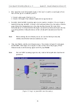
Then click
Next
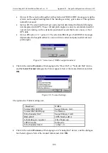
to start the Auto Mount process. The window in Figure 52 will appear,
and the MRU offset angles are computed. A time-out bar shows the progress. When
finished and the found mounting angles look OK, press
Finish
.
Note
The new MRU mounting angles are only valid in the Seapath after download of
parameters.
Figure 52 Step 3 of Auto MRU Axis Orientation
Summary of Contents for Seatex Seapath 200
Page 1: ...Seatex Seapath 200 Installation Manual Issued 2008 06 09 ...
Page 2: ...Blank page ...
Page 4: ...IV Blank page ...
Page 6: ...VI Blank page ...
Page 10: ...X Blank page ...
Page 14: ...XIV Blank page ...
Page 18: ...Seatex Seapath 200 Installation Manual rev 13 Introduction 4 Blank page ...
Page 22: ...Seatex Seapath 200 Installation Manual rev 13 Specifications 8 Blank page ...
Page 53: ...Seatex Seapath 200 Installation Manual rev 13 Installation drawings 39 ...
Page 54: ...Seatex Seapath 200 Installation Manual rev 13 Installation drawings 40 ...
Page 55: ...Seatex Seapath 200 Installation Manual rev 13 Installation drawings 41 ...
Page 56: ...Seatex Seapath 200 Installation Manual rev 13 Installation drawings 42 ...
Page 64: ...Seatex Seapath 200 Installation Manual rev 13 Appendix A Installation worksheet 50 Blank page ...
Page 80: ...Seatex Seapath 200 Installation Manual rev 13 Appendix C Installation of coax connectors 66 ...
Page 81: ...Seatex Seapath 200 Installation Manual rev 13 Appendix C Installation of coax connectors 67 ...
Page 82: ...Seatex Seapath 200 Installation Manual rev 13 Appendix C Installation of coax connectors 68 ...
Page 83: ...Seatex Seapath 200 Installation Manual rev 13 Appendix C Installation of coax connectors 69 ...


