XI
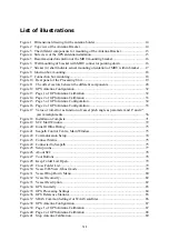
List of illustrations
Figure 1 Dimensional drawing for the antenna holder ........................................................... 14
Figure 2 Top view of the Antenna Bracket ............................................................................ 14
Figure 3 The different components for mounting of the Antenna Bracket ............................ 15
Figure 4 Side view of the GPS antenna installation ............................................................... 15
Figure 5 Recommended orientation of the MRU mounting bracket ...................................... 16
Figure 6 Wall mounting of bracket with MRU connector pointing down ............................. 16
Figure 7 Sticker (4) shall indicate actual mounting orientation of MRU within bracket ...... 17
Figure 8 Junction box mounting............................................................................................. 18
Figure 9 Connection box mounting ........................................................................................ 18
Figure 10 Rear panel of the Processing Unit ......................................................................... 19
Figure 11 The offset vectors between the different components ........................................... 28
Figure 12 GPS Antenna Configuration .................................................................................. 32
Figure 13 Page 1 of GPS Antenna Calibration ...................................................................... 32
Figure 14 Page 2 of GPS Antenna Calibration ...................................................................... 33
Figure 15 Page 3 of GPS Antenna Configuration .................................................................. 34
Figure 16 Page 4 of GPS Antenna Configuration .................................................................. 35
Figure 17 Value of roll-error as function of vessel pitch angle as parameter and 1
°
and 2
°
yaw misalignments ................................................................................................ 36
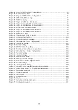
Figure 18 Installation Complete ............................................................................................. 71
Figure 19 SCC Start Window ................................................................................................. 72
Figure 20 Initial Offline Dialog ............................................................................................. 73
Figure 21 Seapath Control Centre, Main Window ................................................................. 73
Figure 22 Communication Setup ............................................................................................ 74
Figure 23 Connect Status ....................................................................................................... 75
Figure 24 Connected to Seapath ............................................................................................ 75
Figure 25 Setup icons ............................................................................................................. 77
Figure 26 About SCC ............................................................................................................. 78
Figure 27 Tool Buttons .......................................................................................................... 78
Figure 28 Keep Folder List Open ........................................................................................... 79
Figure 29 Close Folder List .................................................................................................... 79
Figure 30 Vessel 3D-View, Ghost mode ............................................................................... 79
Figure 31 Vessel Drop Down Menu ...................................................................................... 80
Figure 32 Vessel Geometry .................................................................................................... 82
Figure 33 Vessel Description ................................................................................................. 82
Figure 34 GPS Geometry ....................................................................................................... 83
Figure 35 GPS Processing Settings ........................................................................................ 84
Figure 36 GPS Reference Stations ......................................................................................... 85
Figure 37 SBAS Common Settings for WAAS satellites ...................................................... 86
Figure 38 GPS Antenna Configuration .................................................................................. 87
Figure 39 Page 1 of GPS Antenna Calibration ...................................................................... 87
Figure 40 Page 2 of GPS Antenna Calibration ...................................................................... 88
Figure 41 Stop Antenna Calibration ...................................................................................... 89
Summary of Contents for Seatex Seapath 200
Page 1: ...Seatex Seapath 200 Installation Manual Issued 2008 06 09 ...
Page 2: ...Blank page ...
Page 4: ...IV Blank page ...
Page 6: ...VI Blank page ...
Page 10: ...X Blank page ...
Page 14: ...XIV Blank page ...
Page 18: ...Seatex Seapath 200 Installation Manual rev 13 Introduction 4 Blank page ...
Page 22: ...Seatex Seapath 200 Installation Manual rev 13 Specifications 8 Blank page ...
Page 53: ...Seatex Seapath 200 Installation Manual rev 13 Installation drawings 39 ...
Page 54: ...Seatex Seapath 200 Installation Manual rev 13 Installation drawings 40 ...
Page 55: ...Seatex Seapath 200 Installation Manual rev 13 Installation drawings 41 ...
Page 56: ...Seatex Seapath 200 Installation Manual rev 13 Installation drawings 42 ...
Page 64: ...Seatex Seapath 200 Installation Manual rev 13 Appendix A Installation worksheet 50 Blank page ...
Page 80: ...Seatex Seapath 200 Installation Manual rev 13 Appendix C Installation of coax connectors 66 ...
Page 81: ...Seatex Seapath 200 Installation Manual rev 13 Appendix C Installation of coax connectors 67 ...
Page 82: ...Seatex Seapath 200 Installation Manual rev 13 Appendix C Installation of coax connectors 68 ...
Page 83: ...Seatex Seapath 200 Installation Manual rev 13 Appendix C Installation of coax connectors 69 ...


