Seatex Seapath 200 Installation Manual, rev. 13
Appendix D – Seapath configuration software, SCC
105
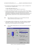
Figure 64 Analog Settings
•
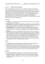
Click in the wanted
MP#
cell and the
Select Measurement Point
dialogue box below
appears. Select the wanted Measurement Point and click
OK
.
Figure 65 Measurement Point
•
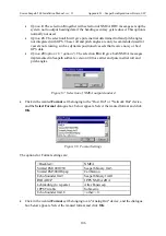
Click in the wanted
Interval
cell belonging to the "Host Out" or "Network Out", and the
Message Interval Settings
dialogue box below appears. Activate the pull-down menu
and choose the wanted Interval. The optional intervals are fixed values between 0.01 and
300 seconds. When finished, click
OK
.
Figure 66 Message Interval Settings
•
Click in the
Option
cell to select the NMEA messages standard and/or the characteristics
of the roll and pitch angles. The following options are available:
•
Option 0
. This is the
default selection and will give NMEA output messages
according to version 2.3.
•
Option 2
. The selection
2
together with selection of NMEA messages will give
messages as implemented in Seapath software version 2.00 or earlier. The NMEA
messages will then be output in NMEA 0183 version 2.00 format.
•
Option 4
. The selection
4
together with selection of NMEA VTG message will add
"Speed through water" in a VHW message. This option is used to show travelled
distance on a Simrad IS15 display.
Summary of Contents for Seatex Seapath 200
Page 1: ...Seatex Seapath 200 Installation Manual Issued 2008 06 09 ...
Page 2: ...Blank page ...
Page 4: ...IV Blank page ...
Page 6: ...VI Blank page ...
Page 10: ...X Blank page ...
Page 14: ...XIV Blank page ...
Page 18: ...Seatex Seapath 200 Installation Manual rev 13 Introduction 4 Blank page ...
Page 22: ...Seatex Seapath 200 Installation Manual rev 13 Specifications 8 Blank page ...
Page 53: ...Seatex Seapath 200 Installation Manual rev 13 Installation drawings 39 ...
Page 54: ...Seatex Seapath 200 Installation Manual rev 13 Installation drawings 40 ...
Page 55: ...Seatex Seapath 200 Installation Manual rev 13 Installation drawings 41 ...
Page 56: ...Seatex Seapath 200 Installation Manual rev 13 Installation drawings 42 ...
Page 64: ...Seatex Seapath 200 Installation Manual rev 13 Appendix A Installation worksheet 50 Blank page ...
Page 80: ...Seatex Seapath 200 Installation Manual rev 13 Appendix C Installation of coax connectors 66 ...
Page 81: ...Seatex Seapath 200 Installation Manual rev 13 Appendix C Installation of coax connectors 67 ...
Page 82: ...Seatex Seapath 200 Installation Manual rev 13 Appendix C Installation of coax connectors 68 ...
Page 83: ...Seatex Seapath 200 Installation Manual rev 13 Appendix C Installation of coax connectors 69 ...


