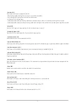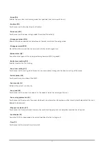
- Tilt (TL)
To retrieve or set the tilt induced latitude and longitude error of the tracker once it has been leveled.
- Track (TR)
To schedule your own tracking orbit.
- Version (VE)
Just to indicate version information of the I/O board and application.
- Maximum velocity (VM)
To retrieve or set the maximum operating velocity for all motors.
- Warm reset (WA)
Performs a reboot with current configuration.
- Watchdog expire (WD)
Lets the watchdog expire and causes a reboot.
- Where (WH)
To retrieves the end of path information for each specified motor.
- Watermark position (WP)
To retrieve the watermark position of all motors (the watermark position is the most recent position of the motor in which the
reference sensor was not activated).
- Range (XT)
To retrieve or set the range for the instrument (azimuth and zenith).
6.2 Serial interface
This chapter describes the serial communication protocol between the SOLYS and the computer or other connected device like
server or data logger. The serial communication is based on client-server architecture. The SOLYS is the server, providing the
information. The computer is the client, sending commands to or receiving data from the instrument.
The communication protocol has three main roles:
• Sending recovery commands to the SOLYS
• Transmission of the instrument’s data (status info) to the computer
• Firmware update
• Instrument hardware configuration
The SOLYS is equipped with a 4-wire RS485 serial interface. The default communication parameters are:
• Baud rate: 19200 bps
• Parity: none
• Data bits: 8
• Stop bits: 1
• Flow control: none
A complete description of the serial communication protocol can be found in the appendix at the end of this manual.
76
Summary of Contents for SOLYS Gear Drive
Page 1: ...SOLYS2 Sun Tracker SOLYS Gear Drive Sun Tracker Instruction Manual...
Page 2: ...2...
Page 4: ...4...
Page 6: ...6...
Page 10: ...10...
Page 39: ...Figure 3 13 Adjustment of the sun sensor 21 0 5 mm 3x 39...
Page 61: ...6 Insert the Ethernet cable Contacts on this side 61...
Page 78: ...78...
Page 80: ...80...
Page 86: ...86...
Page 88: ...88...
Page 112: ......


