


2.2 Considerations and minimum operating area
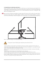
The SOLYS, complete with all accessories attached, requires a substantial amount of unobstructed area to operate properly. This
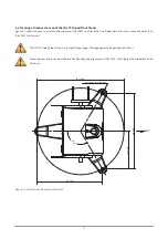
should be kept in mind when deciding where and how the unit is going to be installed. Figure 2.1 shows the minimum operating
area with respect to both the Azimuth and Zenith axis of a SOLYS sun tracker complete with all accessories, including SOLYS Tripod
Floor Stand and Shading Ball Assembly.
Keep in mind that the angle of Azimuth (horizontal) rotation changes during the year. A SOLYS installed in the winter will rotate
further during summer, so make sure no objects will block its movement. To test the SOLYS and to prevent blocking its movement
a rotation lap is performed by the tracker at initial power up (270 ° to the left and 270 ° to the right starting from home position).
figure 2.1. Minimum Operating Area (with Shading Ball Assembly)
It is important to consider the following points before/during the installation of a SOLYS.
• Verify that all cabling is routed properly to prevent cables from catching on any fasteners supports, the SOLYS or instruments.
• Ensure that the surface on which the sun tracker will be mounted is reasonably level, but above all it is very important to createa
very firm base for the feet of the SOLYS Tripod Floor Stand to sit upon.
• Make sure that the site will be free from any obstructions within the operating circle and that there is a clear view to the horizon in
all directions.
• Make sure that the SOLYS and accessories will be accessible for maintenance purposes.
• Make sure that the SOLYS is located in such a way that shadows will not be cast onto the radiometers at any time.
• Ensure that before operation of the SOLYS the Sun Sensor cable and other mounted instrument cabling will not catch on any
fasteners or supports. During the inital power up a rotation lap will be performed to check for blockage or cables which are too short.
• See section 3.24 for cable routing to allow free rotation all year.
Note
1.76 m
1.43 m
14
Summary of Contents for SOLYS Gear Drive
Page 1: ...SOLYS2 Sun Tracker SOLYS Gear Drive Sun Tracker Instruction Manual...
Page 2: ...2...
Page 4: ...4...
Page 6: ...6...
Page 10: ...10...
Page 39: ...Figure 3 13 Adjustment of the sun sensor 21 0 5 mm 3x 39...
Page 61: ...6 Insert the Ethernet cable Contacts on this side 61...
Page 78: ...78...
Page 80: ...80...
Page 86: ...86...
Page 88: ...88...
Page 112: ......


