


2.6.1 Connecting AC/DC power cable
Important,
rotation lap
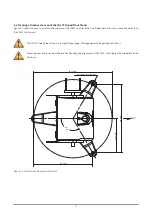
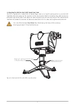
Please be aware that by powering up the SOLYS it will start the initialization procedure. During this procedure it will check the
GPS signal, make a 540 ° rotation and stops in the home position for 60 seconds. It’s advisable to connect the power cable while
checking chapter 2.6.4.
The SOLYS is supplied with 2 waterproof power connectors for both AC and DC power. These connectors are in accordance with safety
regulations for outdoor use. The voltage drop over the cable should not cause the supplied voltage to be out of specifications.
Both the AC and DC connectors are suitable for cable diameters between 6 and 12 mm. For 6 to 9 mm and 9 to 12 mm different
sealing rings are used.
The AC connector is a female type Hirschmann CA 3 LD connector.
The DC connector is a male type Hirschmann CA 3 LS connector.
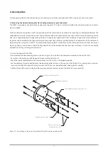
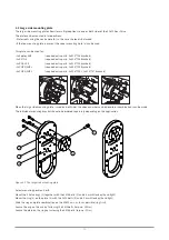
In figure 2.8 the pin numbers are indicated, where pin 3 wil not be used.
Figure 2.8. Pin numbering in male and female power connectors
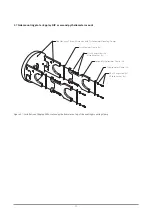
The pin numbers and ground connection for the individual wires are visible whem opening the connector.
Pin 1 = Brown (L)
Pin 1 = Red (+24 VDC)
Pin 2 = Blue (N)
Pin 2 = Black (24 VDC GND)
Pin 3 = not used
Pin 3 = not used
Pin Earth = Green/Yellow (Protected Earth)
Pin Earth = Green/Yellow (Protected Earth)
For AC power:
For DC power:
21
Summary of Contents for SOLYS Gear Drive
Page 1: ...SOLYS2 Sun Tracker SOLYS Gear Drive Sun Tracker Instruction Manual...
Page 2: ...2...
Page 4: ...4...
Page 6: ...6...
Page 10: ...10...
Page 39: ...Figure 3 13 Adjustment of the sun sensor 21 0 5 mm 3x 39...
Page 61: ...6 Insert the Ethernet cable Contacts on this side 61...
Page 78: ...78...
Page 80: ...80...
Page 86: ...86...
Page 88: ...88...
Page 112: ......


