


2.7 Alignment of the SOLYS
Before starting the alignment please verify the following issues
• The 3x M8 bolts which hold the SOLYS Tripod Floor Stand to the actually sun tracker should be fastened by hand only
• The SOLYS has to be leveled (chapter 2.5)
• The SOLYS needs to be supplied with a power source (chapter 2.6)
• The status LED has to be green indicating it has received all GPS information (chapter 2.6.5)
• The power LED has to be green indicating a correct temperature, fan and input voltage (chapter 2.6.5)
• The sun sensor is not connected yet
• Sun with unobstructed sky (DNI >300 W/m2) is required
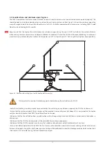
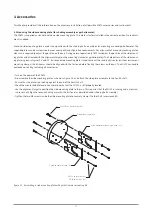
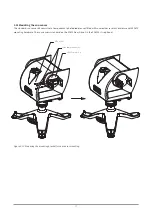
When these requirements are met, the final adjustment can be made by rotating the SOLYS on its Tripod Floor Stand until the sun,
falling through the first alignment target hole, makes a round spot of light around the second alignment target hole (see illustration
4.5). The vertical adjustment of the side mounting plate is a factory setting which should be OK. If the side mounting plates have
been loosened or removed adjust the zenith position as well until the alignment target points at the sun and fasten the screws of the
side mounting plates.
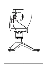
Figure 2.12. Alignment targets
Repeat this alignment after mounting the pyrheliometer (chapter 3.2).
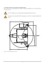
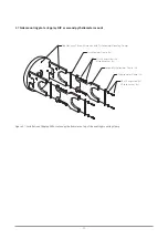
The pyrheliometer also has two alignment targets holes which can be used for a second alignment. Because of the
larger distance between the alignment holes, these are slightly more accurate than on the mounting clamps.
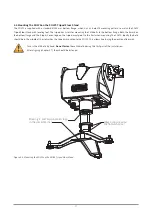
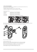
2.8 Secure the Tripod Floor Stand
After the SOLYS is leveled and aligned, it’s time to fix the SOLYS Tripod Floor Stand feet to its firm base. Please perform a re-check
of the leveling and alignment after the tripod feet have been attached to its base.
After the SOLYS is leveled and properly secured recheck all radiometers for proper alignment and leveling.
Side mounting plate
Alignment targets in mounting clamps
Tip
26
Summary of Contents for SOLYS Gear Drive
Page 1: ...SOLYS2 Sun Tracker SOLYS Gear Drive Sun Tracker Instruction Manual...
Page 2: ...2...
Page 4: ...4...
Page 6: ...6...
Page 10: ...10...
Page 39: ...Figure 3 13 Adjustment of the sun sensor 21 0 5 mm 3x 39...
Page 61: ...6 Insert the Ethernet cable Contacts on this side 61...
Page 78: ...78...
Page 80: ...80...
Page 86: ...86...
Page 88: ...88...
Page 112: ......


