


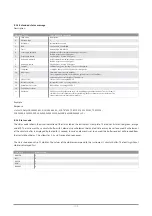


E.2.4 Instrument status
The instrument status value is in hexadecimal notation (0x<hex>) and is divided into a state field (bits 7 - 0) and a set of flags (bits
31 - 8).
Instrument status
State Description
bit 7 - 0
2 encoders
disabled
3
getting encoder offsets failed
4
failed to find ref sensors
5
ref sensor tests failed
6 slipped
7
not functioning (e.g. FU set illegal)
10
waiting for certain conditions to be met before proceeding (temperature, no motor alarm, LL command)
11
in process of stopping prior to entering next state
15
resetting, requesting encoder offsets
16
resetting, getting encoder offsets
19
resetting, moving to reset position
20
resetting, waiting till reset position reached
21
resetting, testing sensors
22
resetting, moving towards ref sensors
23
resetting, globally finding ref sensors
24
resetting, accurately finding ref sensors
25
resetting, accepting reset
26
resetting, waiting in ref and moving over travel range
27
resetting, preparing for selected function (FU)
28
resetting, preparing for selected function (FU, at home)
29
resetting, preparing for selected function (FU, no default circle)
40
accepting motion commands (not operating autonomously)
50
calculating sun position and pointing at sun, if possible (clear)
51
calculating sun position and pointing at sun, if possible (waiting)
52
calculating sun position and pointing at sun, if possible (tracking)
53
calculating sun position and pointing at sun, if possible (rewinding)
255 undefined
Flags Description
bit 8
searching for ref
bit 9
operating autonomously
bit 10
unused
bit 11
valid GPS position
bit 12
valid GPS altitude
bit 13
system time synchronized
bit 14
using sun sensor
bit 15
fan on
bit 16
adjustment ok
bit 31 - 17
unused
110
Summary of Contents for SOLYS Gear Drive
Page 1: ...SOLYS2 Sun Tracker SOLYS Gear Drive Sun Tracker Instruction Manual...
Page 2: ...2...
Page 4: ...4...
Page 6: ...6...
Page 10: ...10...
Page 39: ...Figure 3 13 Adjustment of the sun sensor 21 0 5 mm 3x 39...
Page 61: ...6 Insert the Ethernet cable Contacts on this side 61...
Page 78: ...78...
Page 80: ...80...
Page 86: ...86...
Page 88: ...88...
Page 112: ......


