


20
2. V/F control: It is used in the applications that do not
require very high performance, such as one VFD
controls multiple motors.
Operation mode
Speed control: Control the speed of motor accurately,
related function codes in group A5 should be set.
Torque control: Control the torque of motor accurately,
related function codes in group A5 should be set.
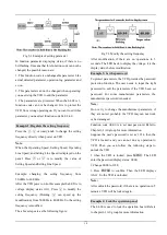
5.2.4 The channels to set the VFD frequency
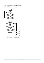
CV100 supports 5 kinds of operating modes in speed
control mode which can be sequenced according to the
priority: Jog>Close loop process operation>PLC
operation>Multiple speed operation>simple operation.
It is shown as follows:
Fig 5-4 Operating mode in speed control mode
The three operating modes provide three basic
frequency sourse.Two of them can use the auxiliary
frequency to stacking and adjusting (except Jog mode),
the descriptions of each mode are as follows:
1) JOG operation:
When the drive is in STOP state, and receives the JOG
command (for example the M key on the panel is
pressed), then the drive jogs at the JOG frequency
(refer to A2.04 and A2.05)
2) Close-loop process operation:
If the close-loop operating function is enabled
(C1.00=1), the drive will select the close-loop
operation mode, that is, it will perform closed-loop
regulation according to the given and feedback value
(refere to Group C1). This mode can be deactived by
the multi-function terminals, and switch to the lower
priority mode.
3) PLC operation
This function is customized, description is omitted.
4) Multi-step (MS) speed operation:
Select Multiple frequency 1
~
15
(
C0.00
~
C0.14
)
to
start Mulitple speed operation by the ON/OFF
combinations of the multi-function terminals (No.27,
28, 29 and 30 function). If all the terminals are
“OFF”,it is in simple operation.
Note:
About the frequency setting channel under speed mode,
please refer to the chapter 6 for detail information
5.3 Power on the Drive for the first
time
5.3.1 Checking before power on
Please wire the drive correctly according to chapter 4
5.3.2 Operations when start up the first time
After checking the wiring and AC supply, switch on
the circuit breaker of the drive to supply AC power to
it. The drive’s panel will display “8.8.8.8.” at first, and
then the contactor closes. If the LED displays the


