Goodrive300-LIFT series inverter
Commissioning guidelines
-82-
on every floor, and adjust creeping speed of elevator (set by multi-step speed) and
S-curve end segment duration).
7.5
Lift running mode
There are two running modes for GD300L: multi-step speed and analog quantity speed. The
multi-step speed mode is mainly used.
7.5.1 Multi-step speed mode (brake and contactor are inverter controlled)
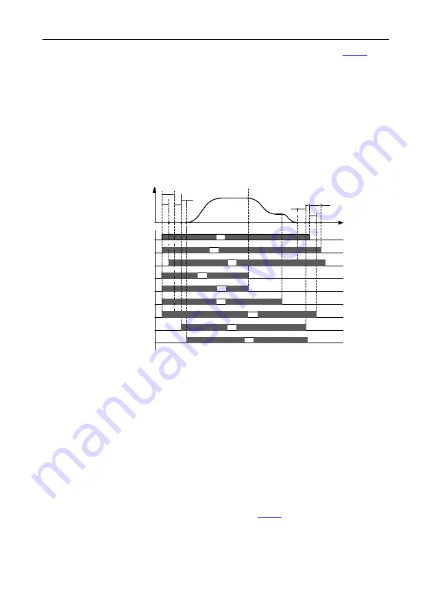
In multi-step speed mode, the speed command can be selected by external multi-step terminals. See
Figure 7-2 for the wiring diagram. Brake and contractor are inverter controlled. Detecting the brake,
contactor feedback signal, and maintenance command are controlled by input terminal (EXM). Run
speeds are given by MS1
–
MS3 and the analog quantity of weighing equipment are applied.
T3 T4
T5
T6
T7
OFF
OFF
OFF
ON
ON
ON
ON
OFF
ON
ON
ON
ON
Brake feedback
Brake control
Running
MS3
MS2
MS1
Contactor feedback
Contactor control
FWD
t
v
T1
T2
T8
OFF
OFF
OFF
OFF
OFF
ON
Figure 7-7 Lift multi-step speed running sequence chart
Running sequence description:
1.
After receiving the FWD and MS1
–
MS3 commands from the controller, the inverter sends the
contactor actuation command and outputs the running signal.
2.
After T1, the inverter detects the contactor actuation feedback.
3.
With the delay of T2 after receiving the running command, the inverter starts zero-speed
output.
4.
The inverter sends the brake control signal with the delay of T3.
5.
After T4, the inverter detects the brake is completely open and then starts ACC at the starting
frequency.
6.
After the controller switches off the speed command (MS1
–
MS3), the inverter decelerates to
stop according to the S curve. If the frequency reaches
, the inverter outputs the brake
switch-off command with the delay of T5, requiring the controller to remove the running
command.


