Goodrive300-LIFT series inverter
Commissioning guidelines
-90-
R
S
T
ENA
FWD
REV
EXM
FB
TB
W
V
U
PE
Y1
Y2
LR
RD
EO
KM1
Brake feedback
Contactor feedback
Maintain
Down
Up
Enable
Fault output
RO1
RO2
RO3
FC(brake control)
TC(contactor control)
PG
M
KM2
GD300L inverter
special for lifts
3PH
380V±15%
50/60Hz
Lift controller
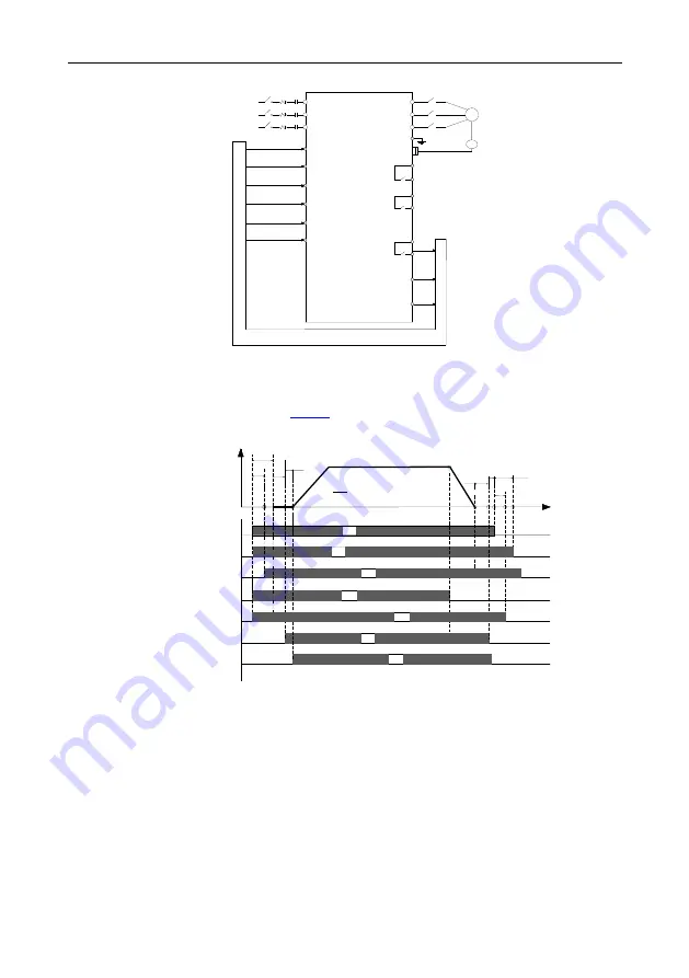
Figure 7-9 Wiring for maintenance running
The maintenance running is the same as the normal timing sequence. The maintenance ACC/DEC is
linear. The maintenance speed is set by
Figure 7-10 shows the maintenance running timing sequence.
T3 T4
T5
T6
T7
OFF
OFF
OFF
ON
ON
ON
ON
OFF
ON
ON
ON
Brake feedback
Brake control
Running
Maintenance
Contactor feedback
Contactor control
FWD
t
v
T1
T2
T8
OFF
OFF
OFF
ON
Figure 7-10 Maintenance running timing sequence
7.5.4 Emergency running
As shown in Figure 7-10, DC UPS connects to the inverter main circuit terminals (+) and (-) through
KM3, D1 and D2 and connects to the control power board through contactor C, the control power
board output connects to the inverter control power input terminals DC+ and DC-, and the main circuit
power connects to the inverter main circuit terminals R, S, and T through KM1.


