


Optic 6 Sport - Page 18
EPA (End Point Adjustment)
Aileron End Points for Aircraft with one Aileron Servo
EPA (End Point Adjustment)
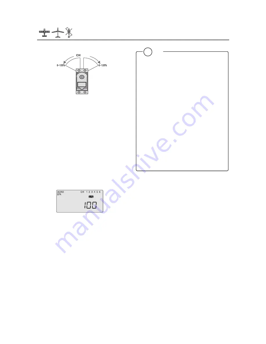
The EPA function is used to set (or limit) the travel of each
servo, and may be set anywhere from 0% and 125% for each
travel direction. Reducing the percentage settings reduces the
total servo throw in that direction. The EPA function is normally
used to prevent any servos from binding at the ends of their
travel.
Note: We recommend that before setting end points you first confirm
the direction of travel for the servo and reverse it if necessary using
the servo reverse function as noted on page 22. Then center all
the control surfaces as closely as possible by adjusting the pushrods
or other mechanical linkages between the servos and the horns on the
control surfaces.
Then fine-tune the centering in the sub trim (S TRM) function screen as
noted on page 22.
In this menu function you can set aileron up and down travel,
up and down elevator travels, right and left rudder travels, open
and closed throttle positions, and aileron up and down travels if
you have a second servo for the left wing.
You can also set the end point travel of flaps and landing gear.
Note: If you change the EPA setting to 0%, you will not have any servo
response in that direction, and will probably crash.
When you first enter the EPA menu, you'll see the default
screen as shown.
The CH (channel) "1" right aileron is flashing and the travel
value sits at 100%. Notice that you can change the R/D indicator
symbol above the value to L/U by moving the stick to the left.
You are about to see how this allows you set the travel
directions independently for each stick motion.
Setting up End Points
1) To set the RIGHT TURN aileron motion (which is upward on
the right wing and downward on the left wing), move the
aileron stick all the way to the right and hold it.
The right wing's aileron should move upward and the letters
"R/D" should appear above the percent value, meaning you
are setting "R" for Right aileron turn.
2) If your servo is stalled or binding, you'll hear a buzzing sound.
Hit the minus -Decrease DATA button until the buzzing stops.
If the servo is not buzzing, leave the setting at 100%. If you
can, choose a location for the pushrod on the servo arm so
that the throw is adjusted in the 90-100% range.
3) To set the maximum travel of the LEFT (downward) motion,
move the aileron stick all the way to the left and hold it. The
letters "L/U" should appear above the percent sign (as shown
in the figure above). ("L" is for Left aileron turn). Again listen
and hit the -Decrease DATA button until the buzzing stops.
If the servo is not buzzing, apply the same value as you did
for the right turn setting.
1~6
!
Tip
The following instructions to set aileron end points is based
on an airplane using one aileron servo for both ailerons.
This servo would be plugged into the #1 channel of the
receiver.
IF your airplane uses two aileron servos, one for each
aileron, and you are in the ACRO mode, do the following:
Plug the right wing servo into ch. 1 and the left wing servo
into ch. 6. Activate the Flaperon mix as shown on page 24.
Adjust the servo's direction of travel and end points
as necessary.
IF your airplane uses two aileron servos, one for each
aileron, and you are in GLID mode plug the right wing
aileron servo into ch. 1 and the left wing aileron servo into
ch. 5. Activate the ADIF, or aileron differential function as
shown shown on page 33.
Adjust the servo's direction of travel and end points as
necessary.


