


138
Appendix
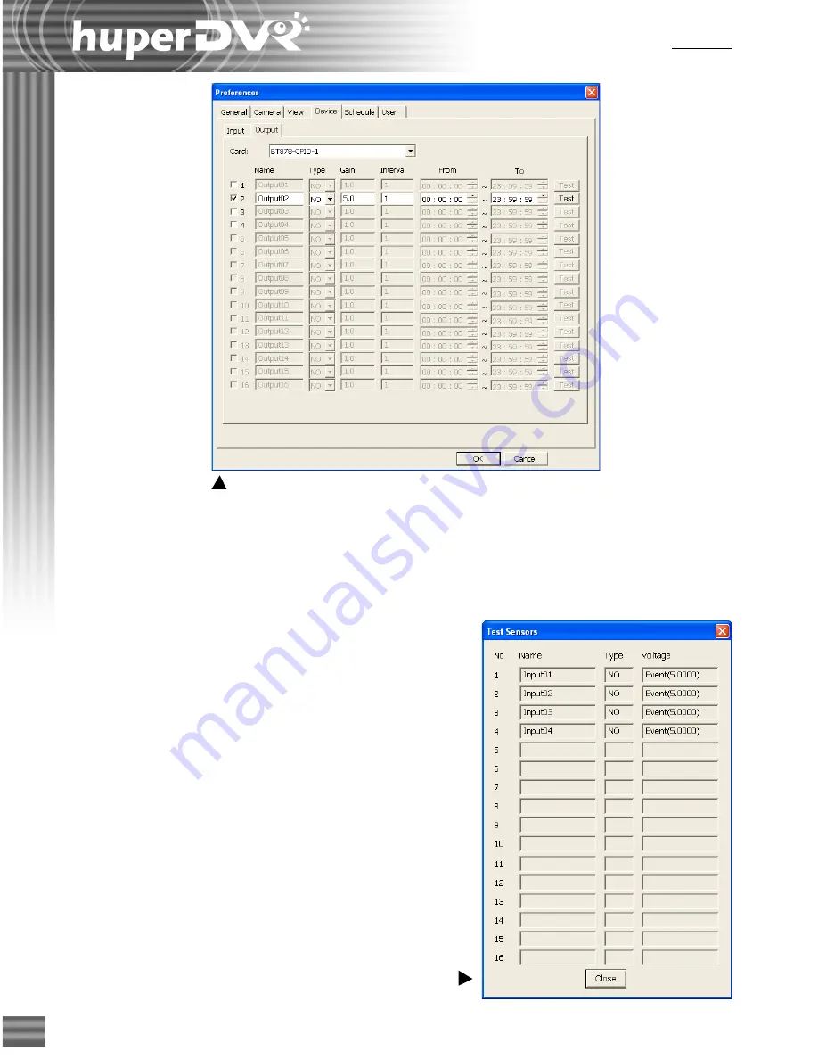
5. Testing the I/O Device Connection
After connecting the I/O ports to I/O devices and
finalizing the settings, click the "
Test
" button on
the "
Preference/Device
" page to check the
connection and settings. Click the "
Test
" button
on the "
Preference/Device/Input
" page to launch
a dialog box displaying the current input voltage of
input devices. (Please refer to Figure 5.) You can
trigger the input device and track the changes of
input voltage in this dialog box. Click the "
Test
"
button on the "
Preference/Device/Output
" page
to change the output voltage. You can check the
behavior of output devices to make sure the
connections and settings are correct.
Figure 4-2 Enable the Output Device
Figure 5 Test Sensors
Summary of Contents for huberDVR 2400
Page 146: ...146 Appendix Output wiring Diagram NC Normal Close setting NO Normal Open setting...
Page 161: ...161 DVR Using RS232 Com Port Connect to RS232 Port DVR using COM Port...
Page 165: ...165 Input Output Pin...
Page 182: ...182 Appendix Input Output Pin...
Page 213: ...213 Step 4 Connect RS232 cable from the RS 232 port of converter device to the computer...
Page 216: ...216 Appendix huperRemote Manual...