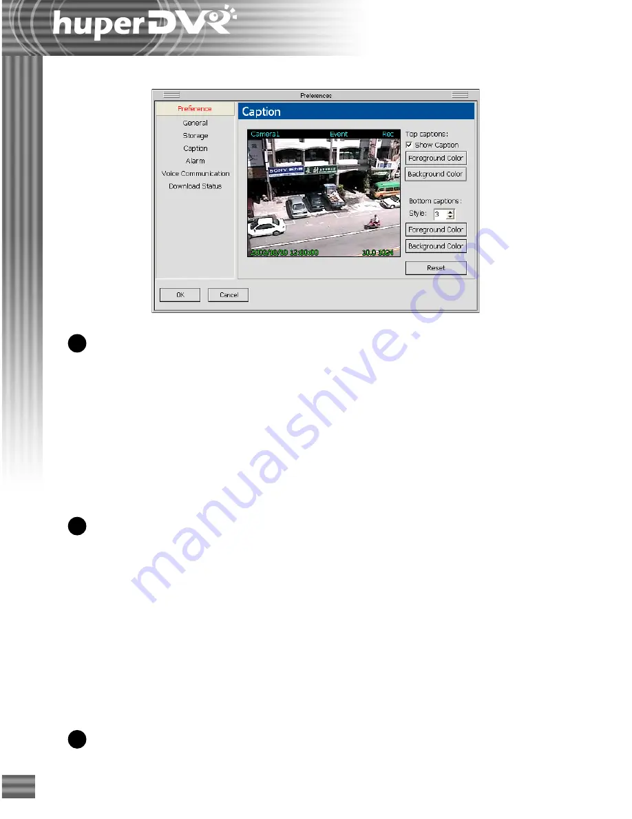
Huper huberDVR 2400 User Manual Download Page 102

102

Caption

Top captions

These are the captions that appear on top of the split-
screen windows. They display the camera name,
detected event, and recording status.

      Show caption

When this option is selected, the top captions will be
displayed on the split-screen windows. To hide these
captions, clear this option.


Foreground Color

Click this button to set the text color for the captions.


Background Color

Click this button to set the color of the text bar.

Bottom captions

These are the captions that appear at the bottom of
the split-screen windows. They display the date and
time, average frame rate, and data rate.

      Style

There are four display styles for the bottom captions:

Style 0: 

Hides the captions.

Style 1:

 Displays the captions with a text bar.

Style 2: 

Displays the captions without a text bar.

Style 3:

 Displays the captions in outline style.


Foreground Color

Click this button to set the text color for the captions.


Background Color

Click this button to set the color of the text bar.

Reset

Click this button to change back to the default
settings.

1

2

3

Summary of Contents for huberDVR 2400

Page 1: ...ess for a particular purpose Huper Laboratories shall not be liable for any error or for incidental or consequential damages in connection with the furnishing performance or use of this documentation...

Page 2: ...o Signal 13 Event Signal 13 Camera Operation Panel 14 Motion Detection Panel 14 Camera Adjustment Panel 15 Operating PTZ Cameras 16 PTZ Control Panel 16 Basic 17 Advanced 18 Auto 20 Custom 21 Settings...

Page 3: ...63 Launching Record Player 63 Program Interface An Overview 63 Types of databases 64 Main database 64 Backed up databases 64 Loading a backed up database 64 Viewing recorded video 65 Selecting the da...

Page 4: ...7 Using Remote Player 88 The User Interface 88 The Camera List Panel 89 The Navigation Panel 90 Viewing Recorded Video 91 Connecting to a DVR Site 92 Selecting the Date of Recording 92 Retrieving and...

Page 5: ...eo recordings from a remote site server 130 Configuring Port settings 130 Downloading video recording from a remote site server 131 Playing back downloaded video recordings 132 Navigation Panel 132 Ch...

Page 6: ...cations such as sending e mail dialing out to a phone etc You can have the same configuration options for all camera sensor devices or specify different settings for each device Record Player Record P...

Page 7: ...red events Identify the target by motion detection Networking Supports multiple levels of access control Allows users to view remote cameras remotely record video and control remote PTZ cameras throug...

Page 8: ...keep fixed days of video recordings Applications Monitoring the babies room a sick family member or the elderly Home and community security Notify security personnel in time by telephone when there i...

Page 9: ...n launched for the first time Site Server will allow any user to have access to the program To restrict the program s access rights only to privileged users click to open the Preferences dialog box th...

Page 10: ...kbar These are Channel Selection buttons This is the Power button Click this button to close the Site Server program These are the video recording R video source V and event detection E indicators If...

Page 11: ...it screen to enlarge its size and temporarily cover its three neighboring screens To restore the split screen back to its normal size double click on it again How split screens are maximized depends o...

Page 12: ...ting signal to the device Map button Click the Map button to switch Site Server to Map mode This mode shows a graphical layout of the site being monitored with clear indications on where the video cam...

Page 13: ...indicator appears green in color it means that the video camera is connected and turned on When a light indicator appears red in color it means that connection to the video camera is lost Event Signal...

Page 14: ...e to return to the Camera Operation Panel Camera Operation Panel The Camera Operation Panel allows you to switch between three different control panels Motion Detection Panel Camera Adjustment Panel a...

Page 15: ...hue saturation adjustment Drag the slider tab to change the hue Drag the slider tab up to increase the saturation level or down to decrease saturation Click here to return to the Camera Operation Pan...

Page 16: ...l if you want to manually control camera panning tilt movements and zooming Advanced The Advanced panel allows you to set the iris level and focus of a selected PTZ camera as well as the camera s pan...

Page 17: ...d the current PTZ camera s angle position Or right click the button to specify a name and record the current PTZ camera s angle position for the preset If there are multiple PTZ cameras use these butt...

Page 18: ...make the lens opening smaller and reduce the amount of light that enters the camera When lesser light enters the camera the video will be darker or may appear underexposed Auto iris Click this button...

Page 19: ...Focus Click this button to focus at the area that is nearer to the camera Click repeatedly if you want to set the focus at the nearest possible distance Far Focus Click this button to focus at the are...

Page 20: ...lick the button to specify a name and set the current camera angle for the preset Switch Left and Right Auto pan has two navigation tours along different sides of the circumference Click this button t...

Page 21: ...button to execute a custom command Auto Pan Speed controls Use these buttons to set the speed for auto panning the PTZ camera Click this button to open the Settings dialog box See page 22 to 25 for de...

Page 22: ...For instance if C1 to C4 are enabled and the remaining numbers are grayed out this means that your capture card is only equipped with 4 video input ports If you have PTZ cameras you need to select wh...

Page 23: ...ice Joystick device If the computer is installed with a joystick device you can use the joystick to control a PTZ camera Select the joystick device from this drop down list to customize it Control Pan...

Page 24: ...PTZ camera through a keyboard Movement Assign the desired keys to use for controlling camera movement such as pan tilt and pause To assign first click your mouse inside the text box then press the de...

Page 25: ...assign PTZ commands to each button You can define up to eight buttons Button number Select a number to customize a button Button name Specify a descriptive name for each button which will appear on th...

Page 26: ...tton Site Server can be enabled to accept two way communication request from a remote client site also running the Remote Viewer program Click the button to open the Talk dialog box where you can conf...

Page 27: ...locations where video cameras sensors and or alarm devices are installed in the site This can help you to instantly identify the location where detected events occurred and take immediate actions whe...

Page 28: ...lled location of each device 6 Click this button to load the map s image file in BMP format 1 Type in a name for the map 2 These are sensor icons Drag them onto the map and drop each of them to the in...

Page 29: ...event its corresponding icon on the map flashes If a camera has been triggered by an event you can click on the flashing camera icon to switch to single view and see what is happening live at the site...

Page 30: ...a Internet Intranet or direct modem connection Storage for surveillance video recordings Allocate disk drives and folders for saving digitally recorded videos Display options These options determine...

Page 31: ...e Server uses a dynamic IP address instead of a static IP address when connecting to the Internet Set the dynamic IP options by clicking Settings See page 30 for more details Reports Generate and e ma...

Page 32: ...Select the checkboxes of the cameras whose recordings you want to save to the selected folder Click the Select all button to select all checkboxes Click the Clear all button to deselect all checkboxes...

Page 33: ...t video files are large in size and may eat up disk space fast When the Auto recycle option is selected Site Server deletes old recordings and frees up disk space for reuse Click the Settings button t...

Page 34: ...sable scaling by selecting the Always display original video resolution option This is how Site Server displays video when this option is selected When displaying a single split screen in full screen...

Page 35: ...events to include in the reports and to whom the reports will be sent Daily Weekly Monthly report Choose whether to send reports on a daily weekly or monthly basis Events detected by Select which even...

Page 36: ...location If you do not want other people to be able to locate your computer over the Web clear this option TCP Port Specify the port of the dynamic Web server Server IP address Specify the IP address...

Page 37: ...your Web browser then enter the dynamic IP server address in the URL field 2 Enter the user ID and password If no user ID and password are specified in the dynamic IP settings click the Submit button...

Page 38: ...camera Camera name Type in a name for identifying a video camera for instance the location where the camera is installed Privilege level Assign each camera with a privilege level to restrict unauthori...

Page 39: ...n be before the event trigger time from 1 second to 10 seconds The pre alarm option is only available in the event recording mode How to enable the pre alarm recording 1 Go to the Preference Camera pa...

Page 40: ...tions option and click Settings Then in the Captions dialog box choose the information to be displayed 2 1 1 2 Note The selected font will be displayed in the actual font size only when the video dime...

Page 41: ...three methods Note The sensor names here cannot be modified Manual trigger This allows you to manually monitor activities in the site You can press Enter to log and or digitally record ongoing activi...

Page 42: ...to select the types of notifications to send See the next section Types of notifications for more details External devices Select this option to enable Site Server to send out signals to external devi...

Page 43: ...at will receive the event notification Click on an e mail address to select it for deletion or modification Add Enter the e mail address in the blank field then click this button to add the e mail add...

Page 44: ...fication Click on a fax number to select it for deletion or modification Add Enter the fax number in the blank field then click this button to add the fax number to the Fax number list Delete Click th...

Page 45: ...llo message Select a wave file or click the Record button to record a hello message Warning message Select a wave file or click the Record button to record a warning message Add Enter the phone number...

Page 46: ...g Event indicator will be displayed on the top central portion of a split screen on the Remote Viewer when an event is detected Change to single view and delay for __ seconds Switches the Site Server...

Page 47: ...the Setting dialog box will be applied Event recording Records detected events Time lapse recording Records video with specified frame rate below 1 fps The range can be from 1 frame per second to 1 fr...

Page 48: ...ustable ranging from value 1 to 100 The higher the value the better is the video quality Fine tuning motion detection settings If you selected the Motion detection option in the Camera tab to enable m...

Page 49: ...High sensitivity means that even the smallest movement will be detected but it could be a false event Careful testing and fine tuning of the sensitivity setting is recommended Noise tolerance Set the...

Page 50: ...ne settings for the marked areas 4 To visually mask out the marked areas where motion will be ignored select the Show mask option Audio capturing device settings Audio tab Click the Audio tab in the P...

Page 51: ...o camera you want to associate with the audio input device A1 to A16 You can only associate one camera per audio recording device Play live sound Each button corresponds to an audio input device Click...

Page 52: ...cameras for display Select any of Site Server s preset layouts Single View 4 Split Screens 9 Split Screens or 16 Split Screens Split screens list This lists the split screens that are displayed on a g...

Page 53: ...e Device tab in the Preferences dialog box to select an I O card and set up the connections to security devices such as sensors and alarms Under the Device tab click the Input tab to configure sensor...

Page 54: ...ensor s analog input Test Click this button to open the Sensor test dialog box to view the actual analog input voltage value The Sensor test dialog box allows you to check the connection status of inp...

Page 55: ...ormal Close or NO Normal Open Gain Specify the output voltage Interval Specify the interval for sending the specified output voltage to the device From To Specify the valid time period for activating...

Page 56: ...schedule click Add 5 In the dialog box that opens set a time schedule for monitoring the camera and select the checkboxes of tasks to be performed within the scheduled time See next page for more det...

Page 57: ...m the drop down list See page 41 for more details on digital recording Detect events by Select the detection methods motion detection sensor detection or Manual trigger See page 42 for details on dete...

Page 58: ...lance schedule for each video camera 1 Choose a video camera by clicking the number button that corresponds to that camera 2 Select the Enable scheduling option 3 From the Type drop down list select B...

Page 59: ...s assigned an operator privilege Can view cameras that were assigned with Operator or Remote user privilege Does not have access rights to the User tab in the Preferences dialog box Does not have righ...

Page 60: ...he Password twice in the provided text boxes 3 Select a Privilege level to assign to the user account 4 Enter a textual Description about the user account To restrict the Site Server program s access...

Page 61: ...r to purge old logs after the specified number of days and free up disk space Disk Information This button displays the amount of remaining disk space Click this button to open the Storage Information...

Page 62: ...How to take a snapshot 1 Right click on a split screen to display the Snapshot popup menu Select the Snapshot menu to open the Snapshot dialog box The snapshot picture is the video frame that you jus...

Page 63: ...eos that have been digitally recorded by Site Server It lists history records by time segments or by the actual occurrence of events At most recordings from 16 different video cameras or 16 recorded e...

Page 64: ...storage Backed up databases These databases contain daily manual backup copies of recorded surveillance video Each day s digital recordings can be backed up in a separate database using huperDVR 2400...

Page 65: ...vious next month 2 Click a date on the calendar to select it 3 Click OK to close the Calendar dialog box 4 The history records of the selected date are automatically retrieved 5 If a day has video rec...

Page 66: ...selected cameras determines the split screen layout of the Record Player program screen as depicted in the table next page To deselect all selected cameras and allow single camera selection only clic...

Page 67: ...ttons on the Camera Selection Panel 2 Click and hold your mouse over a Memory button for 2 seconds The Memory button flashes slowly as it stores your camera selections Release your mouse button when y...

Page 68: ...the program searches for all manually triggered recordings of a specified date and displays them in the History list The History list shows the actual time of video recording and the camera device fro...

Page 69: ...rrently selected in the History list will be played back in the first split screen and the events that follow it in the History list will be played simultaneously in the other split screens Clicking t...

Page 70: ...ect this option to render video data to the VGA display card Clear this option to convert first video data to RGB and then render to the VGA display card Loop playback Select this option to continuous...

Page 71: ...d part of the recorded video Play Pause Plays Pauses the playback at the current frame Stop Terminates the playback and moves to the starting frame Previous Next Frame Moves to the previous next video...

Page 72: ...d mask out parts of the video where motion can be ignored Refer to Fine tuning motion detection settings on page 42 for more details on motion detection Saving video The whole or part of a recorded su...

Page 73: ...is not required the video will automatically play when accessed Note When you click Print and you don t have a printer installed it will prompt a message asking you if you want to install a printer fi...

Page 74: ...VR 2400 Backup Scheduler If access control is enabled in Site Server s Preferences dialog box Users tab users who run the Backup Scheduler program will be prompted to provide login information To be a...

Page 75: ...e recorded surveillance videos in Site Server s Main database See Performing manual backups below for more details Scheduled backup Enables the Backup Scheduler program to perform automatic backups on...

Page 76: ...he ending date time based on your specified file size after clicking Calculate First Last record Allows you to specify the date and time range of video recordings to back up If you selected the Base o...

Page 77: ...the First record and Last record text boxes This button works only when the Base on record size to adjust the last time option is not selected Backup destination Specify the folder location in which t...

Page 78: ...warning message will be displayed 1 2 3 4 Enable scheduling Select this option to activate automatic backups Backup path Specify the destination folder for saving the daily backups Each day s surveill...

Page 79: ...VR site to huperRemote s Camera List Panel then click OK huperRemote will then connect to the specified DVR site and display the remote cameras 5 The DVR site will be added to the Camera List Panel Cl...

Page 80: ...nnected DVR sites Click This closes all connections Monitoring Remote Cameras When huperRemote has successfully established connection with the DVR site s that you added to the Camera List Panel you w...

Page 81: ...lit screen to exchange their positions Maximizing Split Screen Size If there are 4 9 or 16 split screens displayed double click a split screen to enlarge its size and temporarily cover its three neigh...

Page 82: ...en click this button to switch the display to the next group of cameras If there are more remote cameras from other DVR sites that cannot be fit within the program screen click this button to loop the...

Page 83: ...te of a selected camera If your network connection bandwidth is limited it may be helpful to increase the frame rate of the selected camera Triggers a manual event to a remote camera See page 84 for d...

Page 84: ...that displays the remote camera Then click to trigger a manual event to the camera This allows the abnormal activities to be logged and or digitally recorded To record video from selected cameras only...

Page 85: ...isconnecting selected cameras video recording and more To expand the Camera List Panel click To retract and change it back to the normal panel size click again Expanded Camera List Panel Normal size C...

Page 86: ...ed Indicates that only some cameras in a DVR site are selected Panel Indicators Grouping DVR Sites or Remote Cameras You can create a group name to combine certain DVR sites into the same group If you...

Page 87: ...x on the DVR site will then be marked with a red box Now drag and drop the DVR site into the group If you want to add only a single camera from a site into the group select that camera then drag and d...

Page 88: ...also be played in Remote Player At most surveillance video from 16 different video cameras that were recorded at the same time can simultaneously be viewed on screen To change to the Remote Player scr...

Page 89: ...from a connected DVR site and displays the history records of the video recordings of these cameras History records of a chosen date of recording will be displayed under each camera Panel Controls 6...

Page 90: ...ws the currently used playback speed End time Shows the end time of the selected record Jog Bar Allows you to jump directly to any part of the recorded video Drag the slider tab to the desired part of...

Page 91: ...e current video frame and save it as a JPEG or BMP file To capture the current frame from a video first click the split screen that displays the video then click this button This opens the Snapshot di...

Page 92: ...dly until you reach the desired month 3 On the selected month click the desired date Connecting to a DVR Site The DVR Site List keeps track of the URL addresses of DVR servers that you added to huperR...

Page 93: ...interval text box will then appear at the bottom of the Camera List Panel 2 By default Normal type history records are listed in intervals of one hour To change the interval click the Up Down arrow b...

Page 94: ...ecordings from a DVR server 1 Click and choose the type of history records from which to retrieve video recordings To retrieve all recordings of the selected calendar date select Normal Otherwise to r...

Page 95: ...video See page 90 to 91 for details on the different button controls of the Navigation Panel If you want to view multiple video recordings simultaneously hold the Shift or Ctrl key then click the tim...

Page 96: ...t before saving printing or sending the image by e mail To enhance the image drag the Brightness Contrast and Saturation sliders until you get desirable results 3 To save the image click the Save butt...

Page 97: ...t dialog box and connect to a DVR site See page 79 to 80 for more details on adding and connecting to DVRsites Or if you are already connected to a DVR site click the site name in the Camera List Pane...

Page 98: ...to set up the recording schedule for another DVR site Removing Schedules There are three alternative ways you can do to remove some or all of the set recording schedules To remove recording times or...

Page 99: ...menu that appears click DELETE SELECTED To remove several entries from the list press Ctrl and click each unwanted entry Multiple selected entries will be highlighted in yellow To remove them right cl...

Page 100: ...ens set up alarms in your local computer when there are detected events and more Preferences Dialog Box Program window size Choose the appropriate program window size for huperRemote based on the reso...

Page 101: ...g disk space and the amount of disk space already used Recycle storage when disk space is less than When this option is selected old video recordings will be deleted when the hard disk space has reach...

Page 102: ...the color of the text bar Bottom captions These are the captions that appear at the bottom of the split screen windows They display the date and time average frame rate and data rate Style There are f...

Page 103: ...utton then choose the type of sound to use as the alarm Display alert indicator Select this option if you want a blinking alert indicator to be displayed on the split screen window when there is a det...

Page 104: ...lume Drag the slider to adjust the input device s volume Voice playback Device Displays the audio device used by your playback device e g speakers to play back the voice from your counterpart If you h...

Page 105: ...schedules for video recording The entries that are indicated by a play icon are either scheduled recordings which are currently in progress or file downloads which are in progress 1 2 Host Shows the n...

Page 106: ...r accounts in the Site Server that are assigned with at least the Remote User privilege level can access cameras remotely over the Internet Intranet or through direct modem connection Using Remote Vie...

Page 107: ...splay To configure the settings in the Log In dialog box 1 Enter a valid user ID and password Note If the remote DVR Site Server does not enable the access control select the Guest log in check box No...

Page 108: ...ng calls Please refer to the section How to set up an Advanced Connection for the details Make sure to assign a fixed IP address to your LAN card whether it is a global IP address or a local IP addres...

Page 109: ...Site Server that you want to watch via remote 4 Specify the modem driver at the local machine 5 By default All cameras is selected 6 You can select a past connection from the drop down list to fill o...

Page 110: ...nnections icon in the Control Panel window to open Network Connections window 2 Install the driver for the modem device 3 Click the Start button on your Windows taskbar and select Control Panel to ope...

Page 111: ...se fill in the area code and the telephone number of the telephone line connected to the modem 5 Click the Create a new connection item to launch the New Connection Wizard window Click the Next button...

Page 112: ...112 7 Select the Accept incoming connections option then click the Next button 8 In the Connection devices list select the modem driver then click the Next button...

Page 113: ...3 Ch 6 Remote Viewer 9 Select the Allow virtual private connections or Do not allow virtual private connections option then click the Next button 10 Click the Add button to open the New User dialog bo...

Page 114: ...Confirm password then click the OK button to close the dialog box Click the Next button 12 In the Networking software list select the Internet Protocol TCP IP item and click the Properties button to o...

Page 115: ...Viewer 13 Select the Allow calling computer to specify its own IP address option then click the OK button to close the dialog box 14 Click the Next button then click the Finish button to complete the...

Page 116: ...ce 3 Click the Start button then select Settings Network and Dial up Connections Make New Connection to open the Network Connection Wizard dialog window Click the Next button Note If the Location Info...

Page 117: ...117 Ch 6 Remote Viewer 4 Select the Accept incoming connections option then click the Next button 5 In the Connection devices list select the modem driver then click the Next button...

Page 118: ...118 6 Select the Allow virtual private connections or Do not allow virtual private connections option then click the Next button 7 Click the Add button to open the New User dialog box...

Page 119: ...word and Confirm password then click the OK button to close the dialog box Click the Next button 9 In the Networking components list select the Internet Protocol TCP IP item and click the Properties b...

Page 120: ...0 Select the Allow calling computer to specify its own IP address option then click the OK button to close the dialog box 11 Click the Next button then click the Finish button to complete the setup pr...

Page 121: ...this button to connect to a remote DVR site Use the General Control Panel to choose how split screens are displayed enable voice communication play recorded video and customize preference settings See...

Page 122: ...ently in video recording mode at the remote site This mark represents that the video has been recorded to a local machine 1 Split screens Each split screen on the Remote Viewer interface shows the cam...

Page 123: ...button to go back to the default zoom ratio If the PTZ camera does not provide zoom scaling feature click the up or down arrow continuously to zoom in or out Record button Click this button to start r...

Page 124: ...n view click to loop the video feed from the cameras on the split screens Play Remote Live Sound Click to hear remote live sound coming with remote live video Record List button Click to display the l...

Page 125: ...e from the drop down menu Voice Playback Displays the audio device used by your playback device e g speakers to play back the voice from your counterpart You can also adjust the playback device s volu...

Page 126: ...an connect to 16 cameras from 16 different DVR Site Servers Controlling the DVR Site Server desktop remotely 1 Provide a password to the Administrator account in Site Server 2 Install the Remote Viewe...

Page 127: ...om remote cameras Remote Viewer saves them on the local computer s hard drive To retrieve and view the recorded videos click the button A Record list window then appears displaying logs of video recor...

Page 128: ...ext Frame Snapshot button Click this button to capture the current video frame save it as a JPEG file and then display it on the Snapshot Web page Snapshot Web page The Snapshot Web page displays the...

Page 129: ...d Player Remote Record Player allows you to download video recordings from a remote DVR site server and then view them on your local computer Only downloaded video recordings from a remote DVR site se...

Page 130: ...is recommended to use the default values for Command port and Web Server port Click the Default button to restore the default values in the dialog box Downloading and playing back video recordings fro...

Page 131: ...location where you want to save the downloaded video recording Retry Use the arrow keys to specify how many times to retry downloading the video recording when the initial download try fails Download...

Page 132: ...xt Frame Moves to the previous next video frame After clicking the OK button valid User ID and Password may be required before you can click the OK button in the Login dialog box a dialog box will ope...

Page 133: ...riginal speed Fast Motion Increases the playback speed of the video Click once to double 2 x the playback speed Click again to quadruple 4 x the playback speed The maximum speed is 64 x Changing the z...

Page 134: ...of video capture cards Please refer Figure 1 3 and 1 4 positive pole pins are at the side marked with GPIO1 GPIO4 negative pole pins are at the opposite side marked with G The left most pin pair are...

Page 135: ...135 7 8 1 2 JP2 GPIO1 GPIO2 GPIO3 GPIO4 7 8 1 2 JP2 GPIO1 GPIO2 GPIO3 GPIO4 Figure 1 2 I O Ports Figure 1 1 H1004S Video Capture Card...

Page 136: ...136 Appendix P2 AUDIOIN G G G G G G G G GPIO GPIO1 GPIO4 AIN4 AIN1 P2 AUDIOIN G G G G G G G G GPIO GPIO1 GPIO4 AIN4 AIN1 Figure 1 4 I O Ports at the left part Figure 1 3 H4004Q Video Capture Card...

Page 137: ...ncreasing decreasing the voltage from the input device or to the I O port can solve the problem Please note that I O ports can only accept DC Direct Current 4 Setting I O Devices I O devices and I O p...

Page 138: ...vice Input page to launch a dialog box displaying the current input voltage of input devices Please refer to Figure 5 You can trigger the input device and track the changes of input voltage in this di...

Page 139: ...er 3 Issue event notifications In order to include input devices to the normal operation of Site Server you need to select the Sensor detection option in the Detect events by group on the Preference C...

Page 140: ...modification you need to know each setting standing for Below explain the settings one by one 1 SYSTEM Section KeyName Default Description Field_sync 1 Enable it if the capture board has the Field Syn...

Page 141: ...rate but keep better video image quality Disable by default 3 FRAME_RATE Section KeyName Default Description CHIP01 CHIP16 30 Specify the maximum capturing frame rate for each Bt878 chip 30 fps by def...

Page 142: ...maller data size but may reduce the image quality QP 5 Specify the QP value Smaller value gains better image quality but has larger data size Search_level 2 Specify the motion searching method Value 1...

Page 143: ...ame Default Description SAMPLE 8000 Specify the audio smapling rate 8KHz by default BIT 8 Specify the sample resolution 8 bits by default It cound be 8 bits or 16 bits 9 MAILDIMENSION Section Availabl...

Page 144: ...selectable to either isolated or non isolated input The IOC 0404P provides four channels with Form C relay IOC 0404P is excellent for ON OFF control or low power switching applications For easy monito...

Page 145: ...145 Application Wiring The following gives you examples on how to connect the cable to your IOC 0404P modules Input wiring Diagram Isolation Digital Input Dry Contact Input...

Page 146: ...146 Appendix Output wiring Diagram NC Normal Close setting NO Normal Open setting...

Page 147: ...ousing from IOC 0404P as figure 1 2 Fix the IOC 0404P using screw 3 Connect the cable of input output to terminator block as desired 4 Plug terminal block into IOC 0404P as figure 2 5 Check the INPUT...

Page 148: ...148 Appendix Host wiring 1 IOC 0404P to H1004S Please be noted that the red line of cable should connect to the pin2 at the IOC 0404P card and the H1004S card IOC 0404P H1004S H1004S...

Page 149: ...P to H4004Q Please be noted that the red line of cable should connect to the pin2 at the IOC 0404P card and the G pin at the H4004Q card The same wiring for H4016SB H4008DB H416SG and H408DG IOC 0404P...

Page 150: ...150 Appendix IOC 0404P H8008QB H8008QB 3 IOC 0404P to H8008QB Please be noted that the red line of cable should connect to the pin2 at the IOC 0404P card and the G pin at the H8008QB card...

Page 151: ...t channel 4 8 DI4 Input channel 4 Pin no P2 Relay output Description 1 RL1 COM Relay output channel 1 common 2 RL1 NC NO Relay output channel 1 NC or NO 3 RL2 COM Relay output channel 2 common 4 RL2 N...

Page 152: ...ve data RXD 4 Host interface RS232 J1 Signals J1 Transmissiondata TXD 1 Ground 2 3 Receive data RXD 4 Input module dry contact optical isolation select JP1 4 Channels Dry contact Optical isolation Cha...

Page 153: ...el 4 ground 4 Output channel 3 data 5 Output channel 3 ground 6 Output channel 4 data 7 Output channel 4 ground 8 Host interface GPIO J3 Signals J3 Input channel 1 data 1 Input channel 1 ground 2 Inpu...

Page 154: ...gs Input Settings Step 1 Invoke the Preference Device Input setting page Step 2 Select BT878 GPIO 1 item from the card list Step 3 The 4 input ports of IOC 0404P maps to input 1 2 5 and 6 in the setti...

Page 155: ...s Step 1 Invoke the Preference Device Output setting page Step 2 Select BT878 GPIO 1 item from the card list Step 3 The 4 output ports of IOC 0404P maps to output 3 4 7 and 8 in the settings Please do...

Page 156: ...156 Appendix PS If IO 0404P connect to two capture cards the number of output pin are 8 They are output 3 4 7 8 11 12 15 and 16...

Page 157: ...ngth 2500VAC Electrical life min 1 x 10 5 Mechanical life min 1 x 10 7 Power Consumption 110 220 VAC or 5VDC 5W C Communication Port RS232 RS485 Protocol Huper RTU ASCII RS232 1200 115 200 bps RS485 1...

Page 158: ...uction DC 5V Power and Dry ContactTerminals total 8 terminals Relay Output total 5 terminals RS232 RS485 Communication Port and Communication IP DIP Switch AC Power Input DC 5V Power Input RS232 RS485...

Page 159: ...159 Connect to AC power supply Installation 110 220 VAC Power Supply Wiring DC 5V power supply CAN NOT be in use together with the AC power supply...

Page 160: ...160 Appendix DC 5V Power Supply Wiring When 5 relays are concurrently in use for a long time DC 5V power supply CAN NOT be in use together with the AC power supply 5VDC GND COM 5VDC V 5V...

Page 161: ...161 DVR Using RS232 Com Port Connect to RS232 Port DVR using COM Port...

Page 162: ...162 Appendix DVR Using USB to Connect to RS232 Com Port Connect to USB RS232 converter DVR without COM Port...

Page 163: ...163 DVR Using USB to Connect to RS485 Com Port ConnecttoUSB RS485converter DVR without COM Port or for long distanceusage...

Page 164: ...ns 01 3 If NO 4 is ON and others are OFF it means 02 4 If NO 5 is ON and others are OFF it means 04 5 If NO 6 is ON and others are OFF it means 08 6 If NO 7 is ON and others are OFF it means 16 7 If N...

Page 165: ...165 Input Output Pin...

Page 166: ...supply is 110 220 VAC No extra DC power supply is necessary 4 When 5 relay output controls are in long term use an extra 5VDC power supply is necessary 5 Please DO NOT turn on the AC power supply whi...

Page 167: ...Contact Input When 5 relay output controls are in long term use an extra 5VDC power supply is necessary IOB 0805 DI Wiring Example B Fire Alarm Detection Contact Input Using DC Power Supply Fire Alarm...

Page 168: ...tput Control 5 RO controls share the same power supply and accept different levels of voltage All the power supplies must be the same type i e AC or DC Application Example Alarm Indicator AC IOB 0805...

Page 169: ...169 Application Example Small Fan or TV Set under 5A IOB 0805 RO Wiring Example B Small Fan or TV Set under 5A...

Page 170: ...sumption is under 15A such as refrigerators rice cookers microwaves washers small coolers and heaters the AC wire needs to be 2 0 mm 2 As for the large sized appliances like air conditioners and heate...

Page 171: ...der 15A such as refrigerators rice cookers microwaves washers small coolers and heaters the AC wire needs to be 2 0 mm 2 As for the large sized appliances like air conditioners and heaters etc whose p...

Page 172: ...0805 I O box see below 1 Please find the folder bin in the directory C Program Files huperLab huperDVR2400 bin after installation close DVR server 2 Open bin then find the file Live ini see below 3 Cl...

Page 173: ...4 Change Driver00 GPIODevice dll to Driver00 i7k_iorw dll see below 5 Close and save this section 6 After restart DVR site server IO Box can be detected by DVR in the Devices page in Preference see be...

Page 174: ...setting page Step 2 Select the item IOB 0805 I from the controller list Step 3 8 input ports appear in the setting page and their assigned numbers start from 1 to 8 Step 4 Click the Test button to ope...

Page 175: ...setting page Step 2 Select the item IOB 10805 O from the controller list Step 3 5 input ports appear in the setting page and their assigned numbers start from 1 to 5 Step 4 Click the Test button to ex...

Page 176: ...e 5 12 24 VDC Max Load Current 500 ma 2A Per Common Group Power Consumption 5W Communication port RS232 RS485 Protocol Huper RTU ASCII RS232 1200 115 200 bps F RS485 1200 921 6K bps Communication dist...

Page 177: ...Contact Input Signal total 16 Red Indicators DC 5V Power and Dry Contact Terminals Total 16 terminals RS232 RS485 Communication Port and Communication IP DIP Switch DC Power Supply Output Signal Toal...

Page 178: ...178 Appendix Installation DVR Using RS232 Com Port Connect to DC power supply Power consumption 12VDC Connect to RS232 Port DVR using COM Port...

Page 179: ...179 DVR Using USB to Connect to RS232 Com Port Connect to DC power supply Power consumption 12VDC Connect to USB RS232 converter DVR without COM Port...

Page 180: ...180 Appendix DVR Using USB to Connect to RS485 Com Port Connect to DC power supply Power consumption 12VDC ConnecttoUSB RS485converter DVR without COM Port or for long distanceusage...

Page 181: ...y 1 NO 1 NO 5 are node ID a binary system 2 If NO 1 is ON and others are OFF it means 01 3 If NO 2 is ON and others are OFF it means 02 4 If NO 3 is ON and others are OFF it means 04 5 If NO 4 is ON a...

Page 182: ...182 Appendix Input Output Pin...

Page 183: ...ceptable voltage is DC5V DC24V 2 4 DI controls share the same power supply which accepts different levels of voltage starting from DC5V to DC24V Application Example Alarm Detection Contact Input IOB 1...

Page 184: ...ot allowed to connect to VDC The acceptable voltage is DC5V DC24V 2 4 DI controls share the same power supply which accepts different levels of voltage starting from DC5V to DC24V Application Example...

Page 185: ...For the appliances whose power consumption is under 15A such as refrigerators rice cookers microwaves washers small coolers and heaters the AC wire needs to be 2 0 mm 2 As for the large sized applianc...

Page 186: ...1616 I O box see below 1 Please find the folder bin in the directory C Program Files huperLab huperDVR2400 bin after installation close DVR server 2 Open bin then find the file Live ini see below 3 Cl...

Page 187: ...4 Change Driver00 GPIODevice dll to Driver00 i7k_iorw dll see below 5 Close and save this section 6 After restart DVR site server IO Box can be detected by DVR in the Devices page in Preference see be...

Page 188: ...etting page Step 2 Select the item IOB 1616 I from the controller list Step 3 16 input ports appear in the setting page and their assigned numbers start from 1 to 16 Step 4 Click the Test button to op...

Page 189: ...setting page Step 2 Select the item IOB 1616 O from the controller list Step 3 16 input ports appear in the setting page and their assigned numbers start from 1 to 16 Step 4 Click the Test button to e...

Page 190: ...Wide Dynamic Vision Card Functions Description Visibility Makes the video visible even though the field of view is in a low illuminated Enhancement environment especially for night and backlighted si...

Page 191: ...t helps sharpen a blurred field of view caused by focus loss especially if you want to sharpen blurred images or blurred text Sharpness adjustment cannot further enhance a clear field of view nor make...

Page 192: ...you still cannot get a better result after performing Step 4 consider deselecting the Visibility Enhancement enhancement mode option and selecting only the Brightness balance adjustment option Adjust...

Page 193: ...value in the positive range 3 If the video quality is not good enough enable the Visibility Enhancement enhancement option 1 Apply Visibility Enhancement and adjust the Visibility Enhancement level va...

Page 194: ...rpness item in the Process list box to display its settings Step 2 Select deselect the Sharpness check box to enable disable sharpness adjustment Step 3 Adjust the Sharpness level slider to control th...

Page 195: ...ction settings See Figure 4 Figure 4 Noise reduction function Step 1 Select the Noise reduction item in the Process list box to display its settings Step 2 Select deselect the Noise reduction check bo...

Page 196: ...e 5 2 illustrates that the noise reduction process can reduce the video recording size but still maintain the same video quality as Figure 5 1 Figure 5 3 is the original picture in daytime and Figure...

Page 197: ...to draw a rectangle for measuring the size of the small object on the image The width and height values will be displayed Step 4 Select the Ignore larger object check box to ignore moving objects who...

Page 198: ...ronment for testing The left image in Figure A1 1 is the original picture The right image in Figure A1 1 was applied with Visibility Enhancement The company logo and the text in the right image are mo...

Page 199: ...han Figure A2 1 Figure A2 3 shows the Visibility Enhancement settings used in Example A2 1 Figure A1 3 Settings used in Figure A1 1 and A1 2 Figure A2 2 Visibility Enhancement applied Figure A2 3 Sett...

Page 200: ...re Brightness balance Figure A2 8 Enhancement mode applied Figure A2 9 Settings used in Figure A2 7 adjustment to the positive range for Figure A2 7 using the settings shown in Figure A2 9 or apply Vi...

Page 201: ...ility Enhancement applied Figure A2 12 Visibility Enhancement was applied to the whole picture The advertisement paper at the lower half part of the image is more visible but both the left and right s...

Page 202: ...pe of the car in Figure A3 2 is clearer than Figure A3 1 4 Backlighted Environment Example A4 1 Indoor Situation In Figure A4 1 the sunlight spreads through the French windows behind the camera and th...

Page 203: ...ng directly on the street in the actual scene The right image in Figure A4 4 was applied with Visibility Enhancement using the settings shown in Figure A4 5 the right image is almost recovered back to...

Page 204: ...ntrast in Figure A5 1 is weak due to overexposure Figure A5 2 was applied with Visibility Enhancement and the Brightness balance adjustment value was set in the negative range below zero using the set...

Page 205: ...deo signal 1 Vpp 75 switch optional Dimension 119 88 85 09 mm Pin no CN2 Signal Pin no CN2 Signal 1 X 4 Video 7 2 Ground 5 Video 6 3 Video 8 6 Video 5 Connector Pin Assignment 1 Center crimp terminal...

Page 206: ...ideo 16 6 Video 13 2 Box header for 16 channel video input P1 25 26 1 2 Pin no P1 Signal Pin no P1 Signal 1 Video 1 14 Ground 2 Video 14 15 Video 8 3 Video 2 16 Ground 4 Video 15 17 Video 9 5 Video 3...

Page 207: ...24 Ground 12 Ground 25 X 13 Video 7 26 Grounds 3 Box header for 8 channel video input P2 25 26 1 2 4 Box header for 8 channel video input P3 25 26 1 2 Pin no P3 Signal Pin no P3 Signal 1 Video 9 14 Gr...

Page 208: ...o P4 Signal 1 Ground 14 Video 1 2 Video 5 15 Ground 3 Video 9 16 Video 13 4 Ground 17 Video 2 5 Video 6 18 Ground 6 Video 10 19 Video 14 7 Ground 20 Video 3 8 Video 7 21 Ground 9 Video 11 22 Video 15...

Page 209: ...004S x 4 P4 P5 P6 P7 4 8 12 16 H416SG x 1 P1 16 H4016SB x 1 P1 16 H4004QB x 2 P2 P3 4 8 H4008DB x 2 P2 P3 8 16 H8008DB x 2 P2 P3 8 16 H4004QB H4008DB H8008QB Video Input Connector H416SG H4016SB Video...

Page 210: ...each identified by a unique hardware ID You can assign an ID to a PTZ camera by adjusting the ID switch of PTZ camera device Detail please refers to the PTZ camera manual 4 RS 232 pin definition PinN...

Page 211: ...era has been set up and the pan tilt and zoom controls seem not very well You can switch from duplex mode to simplex mode and try again 2 If there are two more PTZ cameras connect to a serial port at...

Page 212: ...of converter device Be sure that the RX and RX lines of RJ11 cable each connects to the DATA and DATA pins of converter device Picture 3 Connectors at the front side of PTZ camera base Note 1 Another...

Page 213: ...213 Step 4 Connect RS232 cable from the RS 232 port of converter device to the computer...

Page 214: ...mand page of Advance PTZ Control Panel to operate the OSD commands of DynaColor dome camera Step 1 Click the icon on the Camera Control Panel of DVR server to display the Advance PTZ Control Panel Ste...

Page 215: ...trol Panel and select the Custom mode The Advance PTZ Control Panel switches to the Custom panel Step 5 Click the Menu button to display the OSD commands Click Up and Down button to navigate menu comm...

Page 216: ...216 Appendix huperRemote Manual...

Page 217: ...for a particular purpose Huper Laboratories shall not be liable for any error or for incidental or consequential damages in connection with the furnishing performance or use of this documentation or...

Page 218: ...eCameraControls 10 Triggering Manual Events to Remote Cameras 11 Recording Surveillance Video 11 The Camera List Panel 12 PanelControls 12 PanelIndicators 13 Grouping DVR Sites or Remote Cameras 13 Th...

Page 219: ...cheduler 24 Setting up the Recording Schedule 24 Removing Schedules 25 Chapter 5 Configuring huperRemote 27 Preferences Dialog Box 27 General 27 Storage 28 Caption 29 Alarm 30 VoiceCommunication 31 Do...

Page 220: ...ther monitor all cameras or only those cameras that have detected abnormal events With huperRemote you can also initiate voice communication with the operator on a remote DVR server trigger manual eve...

Page 221: ...video from remote cameras on your local drive Playback of Surveillance Recordings Retrieve history records from a remote DVR site and download or stream surveillance recordings for playback on your l...

Page 222: ...list to add the DVR site to huperRemote s Camera List Panel then click OK huperRemote will then connect to the specified DVR site and display the remote cameras 5 The DVR site will be added to the Cam...

Page 223: ...nected DVR sites Click This closes all connections Monitoring Remote Cameras When huperRemote has successfully established connection with the DVR site s that you added to the Camera List Panel you wi...

Page 224: ...r split screen to exchange their positions Maximizing Split Screen Size If there are 4 9 or 16 split screens displayed double click a split screen to enlarge its size and temporarily cover its three n...

Page 225: ...lay to the next group of cameras If there are more remote cameras from other DVR sites that cannot be fit within the program screen click this button to loop the display of the cameras After an elapse...

Page 226: ...ame rate of a selected camera If your network connection bandwidth is limited it may be helpful to increase the frame rate of the selected camera Triggers a manual event to a remote camera See page 11...

Page 227: ...t camera To do so first click the split screen that displays the remote camera Then click to trigger a manual event to the camera This allows the abnormal activities to be logged and or digitally reco...

Page 228: ...g disconnecting selected cameras video recording and more To expand the Camera List Panel click To retract and change it back to the normal panel size click again Expanded Camera List Panel Normal siz...

Page 229: ...Indicates that only some cameras in a DVR site are selected Panel Indicators Grouping DVR Sites or Remote Cameras You can create a group name to combine certain DVR sites into the same group If you on...

Page 230: ...box on the DVR site will then be marked with a red box Now drag and drop the DVR site into the group If you want to add only a single camera from a site into the group select that camera then drag an...

Page 231: ...drive can also be played in Remote Player At most surveillance video from 16 different video cameras that were recorded at the same time can simultaneously be viewed on screen To change to the Remote...

Page 232: ...sts the names of remote cameras from a connected DVR site and displays the history records of the video recordings of these cameras History records of a chosen date of recording will be displayed unde...

Page 233: ...nt video frame Current display speed Shows the currently used playback speed End time Shows the end time of the selected record Jog Bar Allows you to jump directly to any part of the recorded video Dr...

Page 234: ...video frame and save it as a JPEG or BMP file To capture the current frame from a video first click the split screen that displays the video then click this button This opens the Snapshot dialog box...

Page 235: ...ad arrow repeatedly until you reach the desired month 3 On the selected month click the desired date Connecting to a DVR Site The DVR Site List keeps track of the URL addresses of DVR servers that you...

Page 236: ...l text box will then appear at the bottom of the Camera List Panel 2 By default Normal type history records are listed in intervals of one hour To change the interval click the Up Down arrow button or...

Page 237: ...play back recordings from a DVR server 1 Click and choose the type of history records from which to retrieve video recordings To retrieve all recordings of the selected calendar date select Normal Ot...

Page 238: ...deo See page 17 for details on the different button controls of the Navigation Panel If you want to view multiple video recordings simultaneously hold the Shift or Ctrl key then click the time segment...

Page 239: ...ed image first before saving printing or sending the image by e mail To enhance the image drag the Brightness Contrast and Saturation sliders until you get desirable results 3 To save the image click...

Page 240: ...ing Schedule To set up a regular schedule for video recording 1 In the huperRemote program window click to open the Connect dialog box and connect to a DVR site See page 6 for more details on adding a...

Page 241: ...ere are three alternative ways you can do to remove some or all of the set recording schedules To remove recording times or days in Scheduler Click to open the Scheduler In the Scheduler dialog box de...

Page 242: ...26 Ch 4 Using the Scheduler To cancel all scheduled recordings Click to open the Preferences dialog box click Storage then click Cancel Schedules...

Page 243: ...splay on split screens set up alarms in your local computer when there are detected events and more Preferences Dialog Box Program window size Choose the appropriate program window size for huperRemot...

Page 244: ...ace and the amount of disk space already used Recycle storage when disk space is less than When this option is selected old video recordings will be deleted when the hard disk space has reached the sp...

Page 245: ...button to set the color of the text bar Bottom captions These are the captions that appear at the bottom of the split screen windows They display the date and time average frame rate and data rate Sty...

Page 246: ...n choose the type of sound to use as the alarm Display alert indicator Select this option if you want a blinking alert indicator to be displayed on the split screen window when there is a detected eve...

Page 247: ...p down menu Volume Drag the slider to adjust the input device s volume Voice playback Device Displays the audio device used by your playback device e g speakers to play back the voice from your counte...

Page 248: ...the following The entries that are indicated by a clock icon are the preset schedules for video recording The entries that are indicated by a play icon are either scheduled recordings which are curren...

Page 249: ...3 Ch 5 Configuring huperRemote End Shows the end time of a schedule or the end time of a video recording Progress Shows the current progress of a scheduled recording or file download in percentage 5 6...

Reviews: