2.
Select the appropriate console device (deselect unused devices):
a.
Choose the “Boot option maintenance menu” choice from the main Boot Manager Menu.
b.
Select the Console Output, Input or Error devices menu item for the device type you
are modifying:
•
“Select Active Console Output Devices”
•
“Select Active Console Input Devices”
•
“Select Active Console Error Devices”
c.
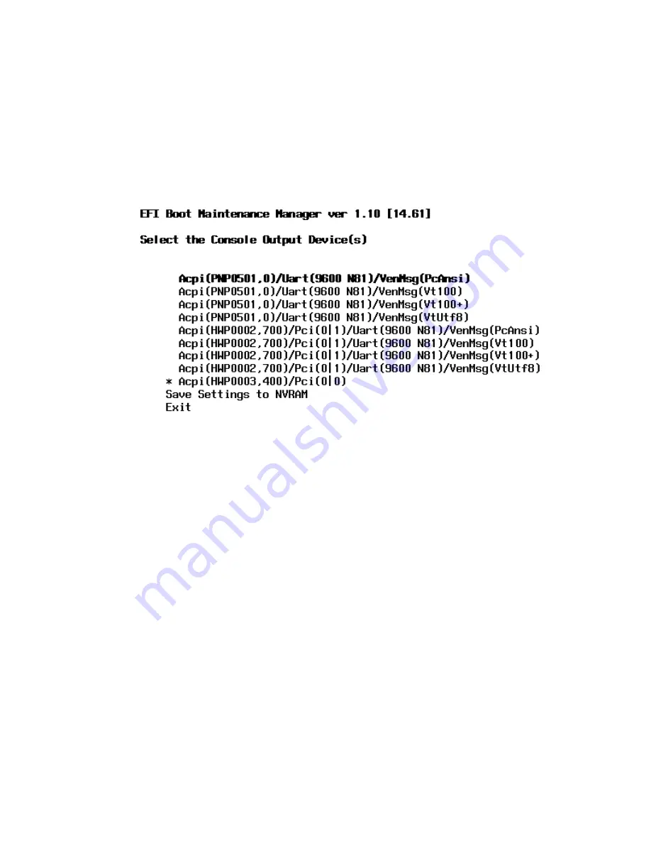
Available devices will be displayed for each menu selection.
Figure 3-36
shows a typical
output of selecting the Console Output Devices menu.
Figure 3-36 Console Output Device menu
d.
Choose the correct device for your system and deselect others. See
“Interface Differences
Between Itanium-based Systems”
for details about choosing the appropriate device.
e.
Select “Save Settings to NVRAM” and then “Exit” to complete the change.
f.
A system reset is required for the changes to take effect.
VGA Consoles
Any device that has a Pci section in its path and does not have a Uart section will be a VGA
device. If you require a VGA console, choose the device and unmark all others.
Figure 3-36
shows
that a VGA device is selected as the console.
Interface Differences Between Itanium-based Systems
Each Itanium-based system has a similar interface with minor differences. Some devices may
not be available on all systems depending on system design or installed options.
Other Console Types
Any device that has a Uart section but no Pci section is a system serial port. To use the system
serial port (if available) as your console device, select the system serial device entry that matches
your console type(PcAnsi, Vt100, Vt100+, VtUtf8) and deselect everything else.
If you choose either a system or MP serial port HP recommends that you use a vt100+ capable
terminal device.
Additional Notes on Console Selection
Each Operating System makes decisions based on the EFI Boot Maintenance Manager menu’s
Select Active Console selections to determine where to send its output. If incorrect console devices
82
Installing the Server
Summary of Contents for Integrity rx7640
Page 8: ...8 ...
Page 12: ...12 ...
Page 13: ...List of Examples 4 1 Single User HP UX Boot 101 7 1 Single User HP UX Boot 181 13 ...
Page 14: ...14 ...
Page 42: ...42 ...
Page 88: ...88 ...
Page 130: ...Figure 5 8 Core I O Button Locations OLR MP Reset 130 Server Troubleshooting ...
Page 140: ...140 ...
Page 176: ...176 ...
Page 184: ...184 ...
Page 191: ...Figure C 3 Planning Grid Computer Room Layout Plan 191 ...


