Installation of Two Slimline DVD+RW Drives.
The HP Integrity rx7640 server can be configured with two slimline DVD+RW drives. Installation
of the slimline DVD+RW drives requires that two core IO card sets are installed in the server.
When the slimline DVD+RW drives are installed, the top drive is associated with cell 1 and the
bottom drive is associated with cell 0.
Installation of the slimline DVD+RW drives requires the following configuration of the data and
power cables in the removable media drive bay.
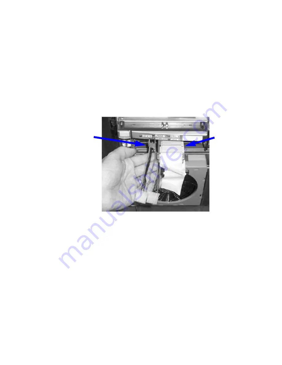
Removable Media Cable Configuration for the Slimline DVD+RW Drives
Installation of the slimline DVD+RW drives requires that both SCSI data cables (Top DVD/DAT
and Bottom DVD) and both power cables are installed into the removable media drive bay. For
proper installation the power cables must be routed to the left of the data cables as shown in
Figure 6-25
.
Figure 6-25 Data and Power Cable Configuration for Slimline DVD Installation
Data Cables:
The Black Line
Indicates the
Correct Length.
Power Cables
The following procedure provides information on configuring the removable media drive bay
cables for use with the slimline DVD+RW drives.
1.
If the cable configuration appears as shown in figure
Figure 6-25
with two power cables and
both the Top DVD/DAT and Bottom DVD data cables, proceed with the installation of the
drives as described in
“Installing the Slimline DVD+RW Drives” (page 165)
.
2.
Turn off power and remove the top cover.
3.
Move the SCSI cables on top of the mass storage backplane out of the way.
4.
Move the removable media data cables out of the way.
5.
Remove the metal removable media bay cover.
6.
Unfold bends marked in orange and flatten the cable marked Bottom DVD.
7.
Fold the Bottom DVD cable at green stripe then nest the Top DVD/DAT and Bottom DVD
cables together and fold as shown in
Figure 6-26
.
Removing and Replacing a Dual Slimline DVD Carrier
163
Summary of Contents for Integrity rx7640
Page 8: ...8 ...
Page 12: ...12 ...
Page 13: ...List of Examples 4 1 Single User HP UX Boot 101 7 1 Single User HP UX Boot 181 13 ...
Page 14: ...14 ...
Page 42: ...42 ...
Page 88: ...88 ...
Page 130: ...Figure 5 8 Core I O Button Locations OLR MP Reset 130 Server Troubleshooting ...
Page 140: ...140 ...
Page 176: ...176 ...
Page 184: ...184 ...
Page 191: ...Figure C 3 Planning Grid Computer Room Layout Plan 191 ...


