7.
Route and connect the server power connector to the site power receptacle.
•
For locking type receptacles, line up the key on the plug with the groove in the receptacle.
•
Push the plug into the receptacle and rotate to lock the connector in place.
WARNING!
Do not set site AC circuit breakers serving the processor cabinets to
ON
before
verifying that the cabinet has been wired into the site AC power supply correctly. Failure
to do so may result in injury to personnel or damage to equipment when AC power is applied
to the cabinet.
8.
Set the site power circuit breaker to
ON
.
9.
Set the server power to
ON
.
10. Check that the indicator light on each power supply is lit.
Connecting AC Input Power
The server can receive AC input power from two different AC power sources. If two separate
power sources are available, the server can be plugged into the separate power sources, increasing
system realibility if one power source fails. The main power source is defined to be A0 and B0.
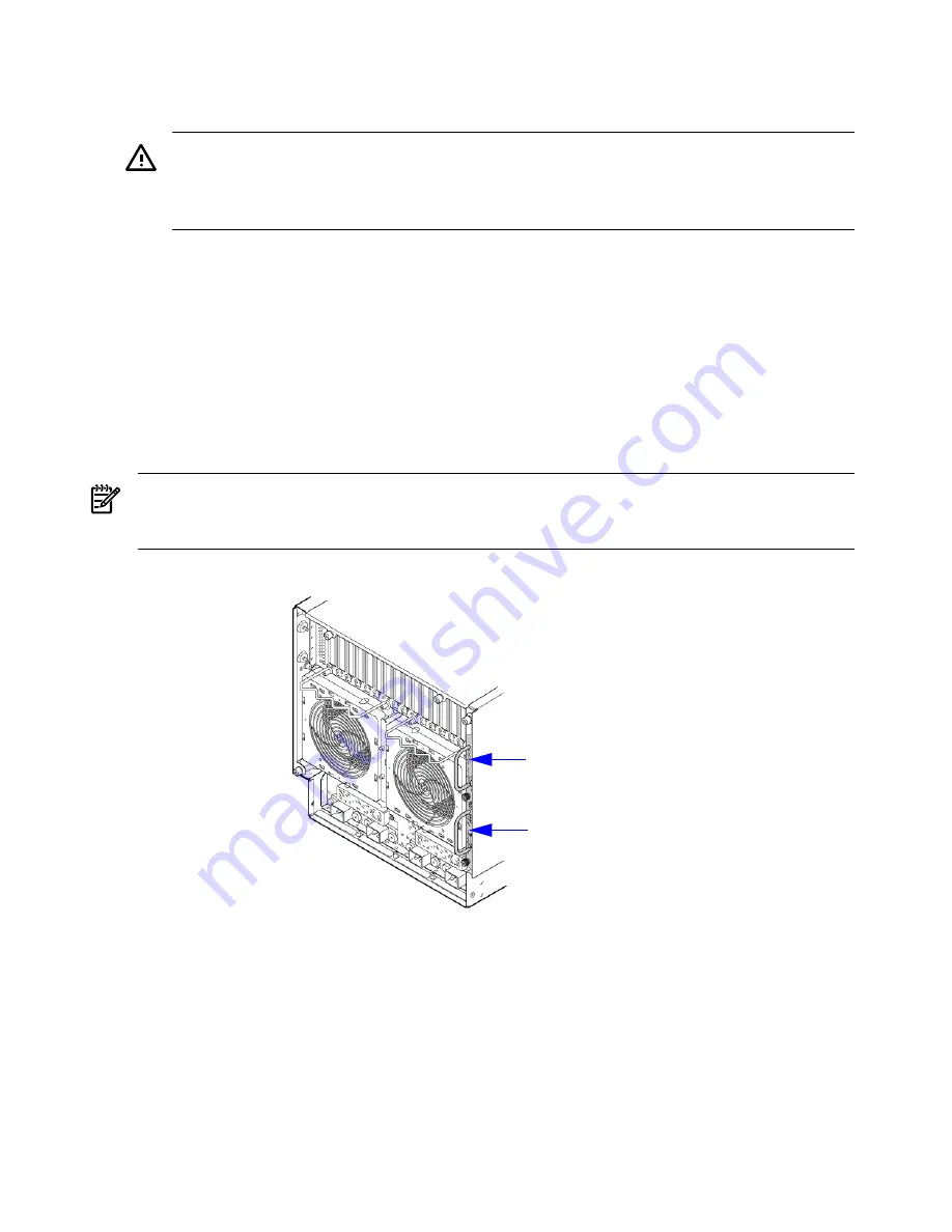
The redundant power source is defined to be A1 and B1. See
Figure 3-25
for the AC power input
label scheme.
NOTE:
When running the server with a single power source, either A0 and B0 or A1 and B1
should be used. All other combinations are not supported. Either combination requires two
power cords.
Figure 3-25 AC Power Input Labeling
MP/SCSI Core I/O card
Slot 0
MP/SCSI Core I/O card
Slot 1
The server has two power cord configurations:
•
All four line cords (preferred configuration)
•
Cords A0 and B0 only
A single-line-cord configuration is not allowed.
The power cord configuration is passed to the operating system using the
pwrgrd
(Power Grid)
command. Each of the five selections in the
pwrgrd
command matches one of the configurations.
The appropriate option should be selected for the actual line cord configuration. With the correct
configuration selected, the LEDs should be green. when the pwrgrd command is invoked, the
following menu is displayed.
MP:CM> pwrgrd
72
Installing the Server
Summary of Contents for Integrity rx7640
Page 8: ...8 ...
Page 12: ...12 ...
Page 13: ...List of Examples 4 1 Single User HP UX Boot 101 7 1 Single User HP UX Boot 181 13 ...
Page 14: ...14 ...
Page 42: ...42 ...
Page 88: ...88 ...
Page 130: ...Figure 5 8 Core I O Button Locations OLR MP Reset 130 Server Troubleshooting ...
Page 140: ...140 ...
Page 176: ...176 ...
Page 184: ...184 ...
Page 191: ...Figure C 3 Planning Grid Computer Room Layout Plan 191 ...


