


-177
Electronics Bay Cooling Fan
Required Tools
•
5
⁄
16
” nut driver or standard screwdriver.
•
5
⁄
64
” allen wrench.
Hardware
• 6-32 x 1
½
” flat head cap screws (x4)
Removing the electronics bay cooling fan
1. Remove the top panel. See
“Removing the top panel” on page 161
2. Remove the side panels. See
“Removing the side panels” on page 162
3. Open the Electronics Bay. See
“Opening the electronics bay” on
4. Touch the metal plate of the electronics bay cover to discharge any static
electricity.
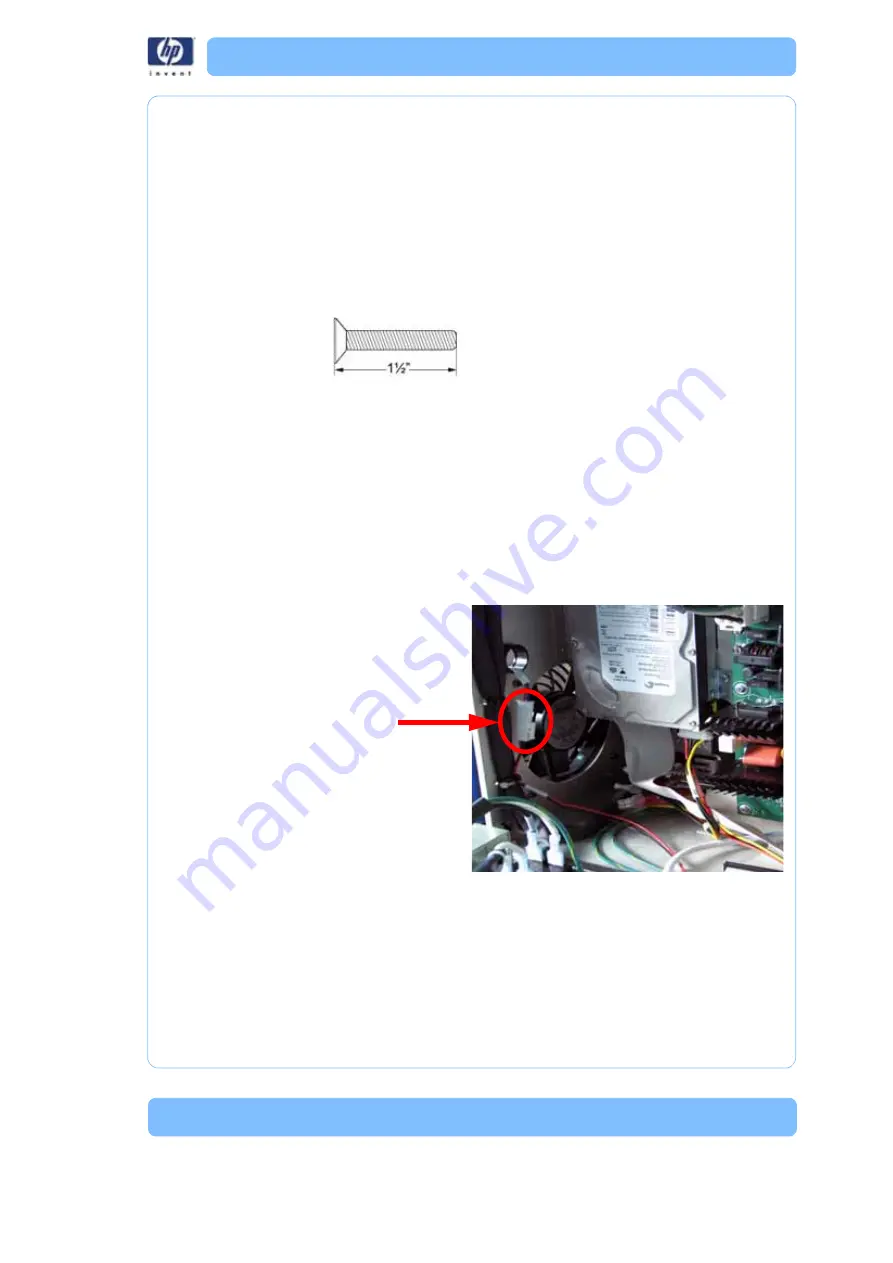
5. Disconnect the P1 cable from the fan. See
Figure 86: Electronics bay cooling fan connector location
6. Using a
5
⁄
64
” allen wrench, remove the 4 mounting screws. See
P1 Connector
Summary of Contents for DESIGNJET 3D
Page 1: ...HP Designjet 3D HP Designjet Color 3D Service Guide ...
Page 3: ......
Page 4: ... 3 ...
Page 16: ... 12 ...
Page 40: ... 24 ...
Page 52: ... 36 ...
Page 70: ... 54 ...
Page 74: ... 58 ...
Page 90: ... 74 ...
Page 172: ... 156 ...
Page 314: ... 298 Figure 272 HP Designjet 3D measurement points and worksheet BL FL FR BR ...
Page 315: ... 299 Figure 273 HP Designjet Color 3D measurement points and worksheet BL FL FR BR ...
Page 349: ... 333 Figure 316 HP Designjet 3D measurement points and worksheet BL FL FR BR ...
Page 350: ... 334 Figure 317 HP Designjet Color 3D measurement points and worksheet BL FL FR BR ...
Page 352: ... 336 ...
Page 404: ... 388 Figure 402 HP Designjet 3D measurement points and worksheet BL FL FR BR ...
Page 405: ... 389 Figure 403 HP Designjet Color 3D measurement points and worksheet BL FL FR BR ...
Page 458: ... 442 ...


