


3
−
84
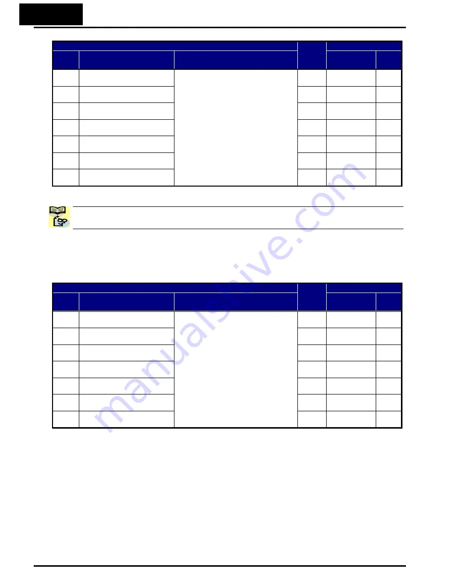
“C” Function
Run
Mode
Edit
Defaults
Func.
Code
Name
Description
Lnitial data
Units
C011
Input [1] active state
Select logic conversion, two option
codes:
00
…
normally open [NO]
01
…
normally closed [NC]
U
00
−
C012
Input [2] active state
U
00
−
C013
Input [3] active state
U
00
−
C014
Input [4] active state
U
00
−
C015
Input [5] active state
U
00
−
C016
Input [6] active state
U
00
−
C017
Input [7] active state
U
00
−
NOTE: An input terminal configured for option code
18
([RS] Reset command) cannot be
configured for normally closed operation.
Note: This response time is disregarded when power-on or reset. For example, when the
power is up when FW terminal is on, then the operation starts regardless this response
time as soon as the internal reset process is completed.
“C” Function
Run
Mode
Edit
Defaults
Func.
Code
Name
Description
Lnitial data
Units
C160
Input [1] response time
Sets response time of each input
terminal, set range:
0
(x 2 [ms]) to
200
(x 2 [ms])
(0 to 400 [ms])
U
1.
−
C161
Input [2] response time
U
1.
−
C162
Input [3] response time
U
1.
−
C163
Input [4] response time
U
1.
−
C164
Input [5] response time
U
1.
−
C165
Input [6] response time
U
1.
−
C166
Input [7] response time
U
1.
−
Intelligent Input Terminal Overview
Each of the seven intelligent terminals may be assigned any of the options in the
following table. When you program one of the option codes for terminal assignments
C001
to
C007
, the respective terminal assumes the function role of that option code. The
terminal functions have a symbol or abbreviation that we use to label a terminal using
that function. For example, the “Forward Run” command is [FW]. The physical label on
the terminal block connector is simply 1, 2, 3, 4, 5, 6, or 7. However, schematic examples
in this manual also use the terminal symbol (such as [FW]) to show the assigned option.
The option codes for
C011
to
C017
determines the active state of the logical input (active
high or active low).
Summary of Contents for WJ200 Series Software
Page 19: ...xviii Revisions Revision History Table No Revision Comments Date of Issue Operation Manual No ...
Page 295: ...4 92 Safe Stop Function To be finalized after TUV approval ...
Page 296: ...5 1 5 Inverter System Accessories In This Chapter page Introduction 2 Component Description 3 ...
Page 322: ...A 1 A Glossary and Bibliography In This Appendix page Glossary 2 Bibliography 8 ...
Page 378: ...B 49 Note 2 Be sure not to write into above 1F02h to 1F1Dh ...


