4-23
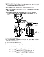
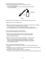
(D) Pull out the viscometer IN-side tube (mark G) from viscometer. (The ink in tube will
slightly drip: Fit wiping paper to the end of tube. No reverse flow of ink will occur inside
the viscometer.)
(E) Immediately lift the end of removed tube higher than the level of liquid in main
container, and then continue this for at least 10 seconds (to return the ink in tube to
the main container).
(F) When the ink has drained from tube and air enters it, release the tube. When air enters
the tube, no reverse flow of ink will occur even if the tube hangs down.
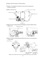
2 Disposing of ink inside viscometer
Remove any ink remaining inside before removing the viscometer.
(A) Turn power on.
(B) Use “Solenoid Valve/Pump Test” screen of “Maintenance Work” to turn on the pump
to MV4, in that order, and operate them for at least 10 seconds. (The ink remaining
in viscometer will return to the main container.)
(C) Turn power off.
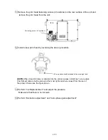
3 Unplugging connectors
Caution: Do not perform this work with power turned on: Doing so will cause
“Viscometer Temperature Sensor Fault” to occur.
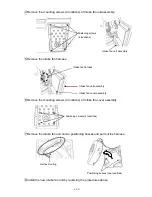
Unplug the connectors of lead wires at the back of circulation unit, and pull them
out forward through the grommet hole.
Proximity sensor: 4-pin; Thermistor: 2-pin (blue/black); Coil: 2-pin (blue/black)
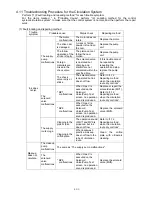
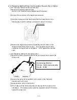
4 Removing viscometer
Remove the two setscrews from viscometer, and then pull the viscometer out
forward.
Caution: Take care that neither the O-ring nor squeezing pin remains in the
circulation unit: Remove both of them.
O-ring
Squeezing pin
Viscometer OUT side
Summary of Contents for IJ RX2
Page 1: ...Service Manual HITACHI Printer Model RX2 Revision Feb 2014 Version A ...
Page 13: ...1 8 2 External views Rear side 1 2 2 Main body internal ...
Page 14: ...1 9 1 2 3 Print head ...
Page 101: ...3 26 Circuit diagram of EZJ127A ...
Page 102: ...3 27 Circuit diagram of EZJ127B ...
Page 116: ...3 41 Circuit diagram of EZJ129 ...
Page 164: ...4 40 5 Reset the time of the R air filter to 0 on the Parts usage time management screen ...
Page 247: ...7 Attached Drawing 7 1 Circulation System Diagram Circulation System Diagram 7 1 ...
Page 249: ...7 3 7 2 2 Electrical Connection Diagram RX2 B Basic model 7 3 ...


