


2-14
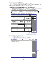
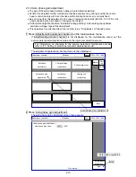
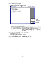
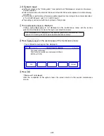
3 Press Automatic acquisition.
During automatic acquisition, “acquisition” is displayed as the processing state.
Auto-phase detection voltage gain is automatically adjusted in the IJ printer.
A target of the auto-
phase gain value is about from “20” to “40” (65μm).
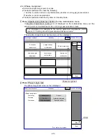
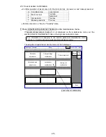
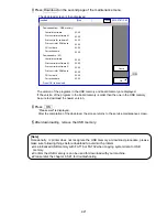
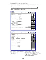
4 After the completion of the automatic adjustment, when the Back key is pressed,
the auto phase detection voltage is output and therefore, confirm the waveform by
an oscilloscope.
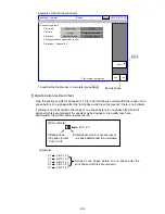
Using the oscilloscope, confirm that the voltage of TP1 (APH voltage) on the EZJ125 board
is from 8 to 10 V as the maximum voltage, 2 V or less as the minimum voltage, and is
“normal” as shown in the following figure.
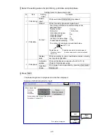
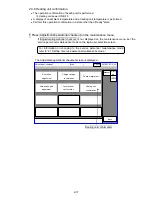
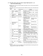
5 When the automatic adjustment is not normally completed or the wave form is
“abnormality”, confirm that the periphery of the gutter part is made dirty with ink or
makeup. When dirtiness or the like is present, wash the periphery of the gutter
part, surely dry it and then, perform the automatic-adjustment again.
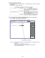
Numerical values of the auto phase gain value can also be input by a ten-key. To the value
set at present, if the auto phase gain value is set large, the gain becomes high, whereas if it
is set small, the gain becomes low.
When the “return” key is input, the auto phase
detection voltage is output and the auto phase gain value is reflected.
For the position of the board and test pins, refer to
“3.3.2 EZJ125. board.”
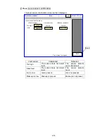
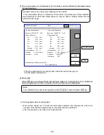
Normal
Maximum voltage
from 8 to 10 V
Noise small
Noise large
Abnormal
10ms
Minimum voltage
2 V or less
Proc. status: Acquisition
Summary of Contents for IJ RX2
Page 1: ...Service Manual HITACHI Printer Model RX2 Revision Feb 2014 Version A ...
Page 13: ...1 8 2 External views Rear side 1 2 2 Main body internal ...
Page 14: ...1 9 1 2 3 Print head ...
Page 101: ...3 26 Circuit diagram of EZJ127A ...
Page 102: ...3 27 Circuit diagram of EZJ127B ...
Page 116: ...3 41 Circuit diagram of EZJ129 ...
Page 164: ...4 40 5 Reset the time of the R air filter to 0 on the Parts usage time management screen ...
Page 247: ...7 Attached Drawing 7 1 Circulation System Diagram Circulation System Diagram 7 1 ...
Page 249: ...7 3 7 2 2 Electrical Connection Diagram RX2 B Basic model 7 3 ...


