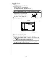
3-21
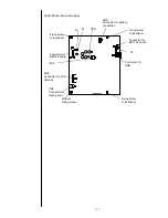
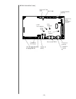
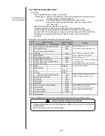
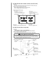
[Setting of switch/check point/LED display and the like]
- Setting of switch
[SW1]
<
P
rint target sensor >
- When supplying power from the IJ printer :
Set as shown in the following table depending on the output form of the print
target sensor.
Output form
SW1
– 5
SW1
– 6
Open collector
(
NPN
)
ON
OFF
Open collector
(
PNP
)
OFF
ON
- When using the external dedicated power supply:
Set as shown in the following table is not depending on the output form of the
print target sensor.
Output form
SW1
– 5
SW1
– 6
Open collector
(
NPN
)
OFF
OFF
Open collector
(
PNP
)
OFF
OFF
<
R
otary encoder >
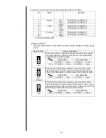
- When supplying power from the IJ printer :
Set as shown in the following table depending on the output form of the rotary
encoder.
- When using the external dedicated power supply :
Irrespective of the output form of the rotary encoder, set as shown in the
following table depending on the power supply voltage.
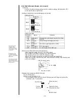
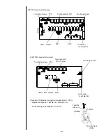
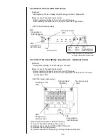
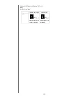
[SW2]
Switching that the input signal connection is NPN/PNP is set.
*) Input signal: Print stop, Reciprocative printing, Deflection voltage ON/OFF,
Run, Reset , Stop
Input / Output NPN
Input / Output PNP
DSW2
Both of bits are put on the bottom
Both of bits are put on the up position.
Input NPN / Output PNP
Input PNP / Output NPN
DSW2
Set only the right bit to the up position.
Set only the left bit to the up position.
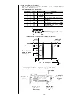
SW1
Set content
Default
Bit 1
Setting is performed according to the specification of the encoder.
ON
Bit2
(Refer to the setting by types of the specification described below.)
OFF
Bit3
Setting is performed according to the specification of the print target detector .
ON
Bit4
Setting is performed according to the specification of the encoder.
OFF
Bit5
Setting is performed according to the specification of Print target
detector.
ON
Bit6
(Refer to the setting by types of the specification described below.)
OFF
Bit7
Reserved (set to OFF)
OFF
Bit8
Print target detector signal noise filter setting
( Time constant: t = 2.2 millisecond)
OFF
Output form
SW1 - 1
SW1
– 2
SW1 - 3
SW1 - 4
Totem pole
OFF
OFF
ON
ON
Open collector
ON
OFF
ON
OFF
Power supply voltage
SW1 - 1
SW1 - 2
SW1 - 3
SW1 - 4
DC 12V
OFF
ON
ON
OFF
DC 24V
OFF
OFF
ON
OFF
ON
OFF
ON
4
3
2
1
8
7
6
5
Mark
Mark
Mark
Mark
Summary of Contents for IJ RX2
Page 1: ...Service Manual HITACHI Printer Model RX2 Revision Feb 2014 Version A ...
Page 13: ...1 8 2 External views Rear side 1 2 2 Main body internal ...
Page 14: ...1 9 1 2 3 Print head ...
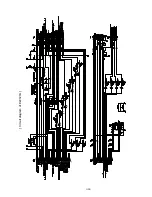
Page 101: ...3 26 Circuit diagram of EZJ127A ...
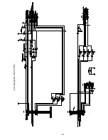
Page 102: ...3 27 Circuit diagram of EZJ127B ...
Page 116: ...3 41 Circuit diagram of EZJ129 ...
Page 164: ...4 40 5 Reset the time of the R air filter to 0 on the Parts usage time management screen ...
Page 247: ...7 Attached Drawing 7 1 Circulation System Diagram Circulation System Diagram 7 1 ...
Page 249: ...7 3 7 2 2 Electrical Connection Diagram RX2 B Basic model 7 3 ...

