


3-18
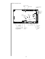
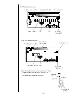
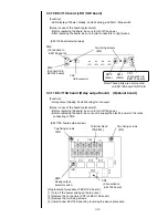
3.3.6 EZJ125 board (Nozzle drive board)
[Function]
- Control of nozzle (charging voltage control, excitation voltage, APH detection, PTC
control and the like) is performed.
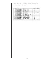
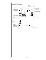
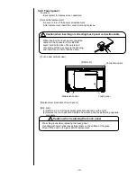
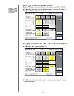
[Setting of switch/check point/LED display and the like]
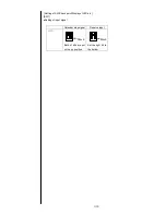
- Setting of switch
Nozzle size
65µm
DSW1
Set both bits up.
DSW2
Set both bits up.
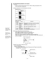
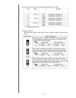
- Check point/ LED
Reference
number
Name
Contents
TP1
APH signal
Charged amount detection signal of ink drops
TP3
GND
Ground
TP12
Charging
signal
Character signal charging ink drops
TP14
Excitation
signal
Sine wave signal applied to a nozzle
TP15
PTC signal
PTC drive signal
LED1
APH signal
For APH signal check with eyes
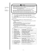
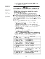
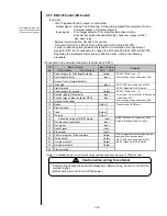
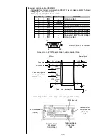
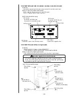
[Note in case of the EZJ125 board replacement]
- When replacing boards, be sure to turn off the power.
- Set up DSW1 and DSW2 according to the nozzle diameter.
- After replacing the board, confirm the charging voltage.
- Perform the excitation adjustment and the auto phase gain adjustment.
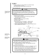
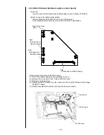
- When removing the connector from CN2, CN3 and CN5, hold the socket housing and
pull it out in straight.
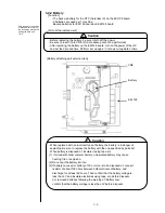
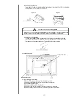
[Replacement procedure of EZJ125 board]
(1) Turn off the power.
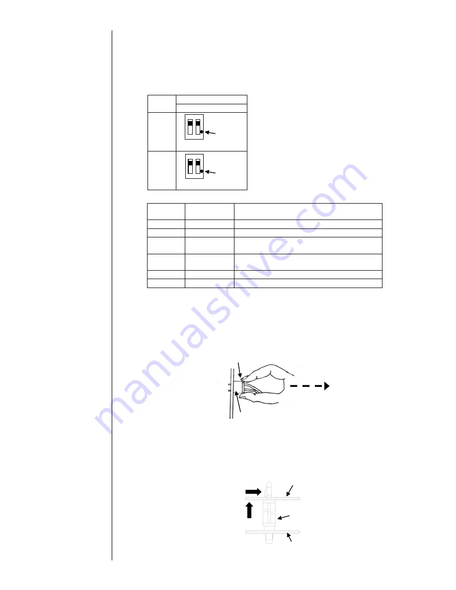
(2) Remove the protective cover.
*) As the drawing below, push the hook of fixing spacer with finger and pull up the
protective cover. (Two spacers)
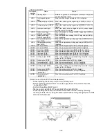
Protective cover
EZJ125 board
Spacer for fixing
the protective cover
Push the hook
Pull up
the cover
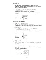
With respect to the
excitation adjustment,
refer to “2.3.1 Excitation
adjustment”.
With respect to the
charging voltage
confirmation, refer to
“2.3.2 Charging voltage
confirmation
”.
With respect to the auto
phase gain adjustment,
refer to “2.3.4 Auto phase
gain adjustment
”.
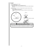
Hold the socket housing
Connector on board
Mark
Mark
Summary of Contents for IJ RX2
Page 1: ...Service Manual HITACHI Printer Model RX2 Revision Feb 2014 Version A ...
Page 13: ...1 8 2 External views Rear side 1 2 2 Main body internal ...
Page 14: ...1 9 1 2 3 Print head ...
Page 101: ...3 26 Circuit diagram of EZJ127A ...
Page 102: ...3 27 Circuit diagram of EZJ127B ...
Page 116: ...3 41 Circuit diagram of EZJ129 ...
Page 164: ...4 40 5 Reset the time of the R air filter to 0 on the Parts usage time management screen ...
Page 247: ...7 Attached Drawing 7 1 Circulation System Diagram Circulation System Diagram 7 1 ...
Page 249: ...7 3 7 2 2 Electrical Connection Diagram RX2 B Basic model 7 3 ...


