


2-13
2.3.4 Auto phase gain adjustment
●
The gain of the auto phase detection voltage is automatically adjusted.
●
Perform this adjustment after confirmation that the periphery of a gutter part within the nozzle
head is not made dirty with ink or the like and the printing head cover is correctly fixed.
●
Be sure to perform this adjustment in the case of replacing the boards (EZJ126, 125, 128) or the
nozzle (including the print head) or changing the ink type.
●
Perform this adjustment before “Excitation voltage setting”. After setting the optimum
excitation voltage, repeat this adjustment.
●
This adjustment is performed when the IJ printer is in a “Drop adjust” or “Standby” state.
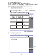
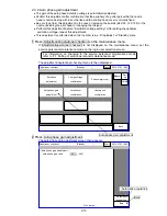
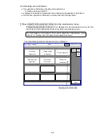
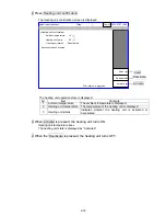
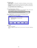
1 Press Adjustment/operational checkout on the maintenance menu.
If Adjustment/operational checkout is not displayed on the maintenance menu, set the
service personnel maintenance mode on the login user selection screen.
The adjustment/operational checkout menu is then displayed.
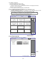
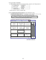
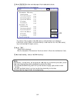
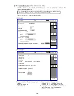
2 Press Auto-phase gain adjustment.
The auto-phase gain adjustment screen then appears.
For information on changing to the service personnel maintenance mode,
refer to “2.1 Setting of service personnel maintenance mode.”
Manual
Start
up
HOME
Back
Adjust./oper. checkout
Excitation
adjustment
Charge voltage
confirmation
Phase margin test
Heating unit
confirmation
Auto-phase gain
adjustment
Level sensor
confirmation
[Standby
]
2015.07.07 12:45
Com=0
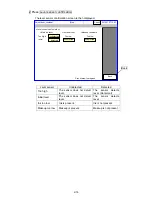
Auto-phase gain adjustment
Back
Adjust./oper. checkout
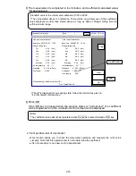
<Auto-phase gain adjustment>
40
Auto-phase gain value
(2-62)
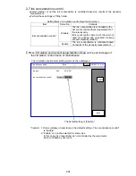
Automatic
acquisition
Proc. status:
[Standby
]
2015.07.07 12:45
Com=0
Back
Automatic acquisition
Summary of Contents for IJ RX2
Page 1: ...Service Manual HITACHI Printer Model RX2 Revision Feb 2014 Version A ...
Page 13: ...1 8 2 External views Rear side 1 2 2 Main body internal ...
Page 14: ...1 9 1 2 3 Print head ...
Page 101: ...3 26 Circuit diagram of EZJ127A ...
Page 102: ...3 27 Circuit diagram of EZJ127B ...
Page 116: ...3 41 Circuit diagram of EZJ129 ...
Page 164: ...4 40 5 Reset the time of the R air filter to 0 on the Parts usage time management screen ...
Page 247: ...7 Attached Drawing 7 1 Circulation System Diagram Circulation System Diagram 7 1 ...
Page 249: ...7 3 7 2 2 Electrical Connection Diagram RX2 B Basic model 7 3 ...


