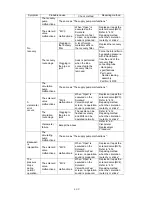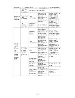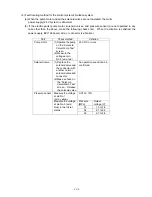
4-27
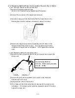
4.10 Print Head Replacement Procedure
1
Carry out “ink drainage.”
2 Turn off the power supply.
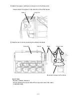
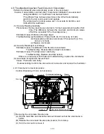
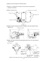
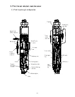
3 Open the maintenance cover and remove the print head connectors (5 locations) in the
control area.
4
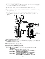
Remove the side cover and the print head connectors (4 locations).
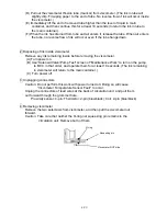
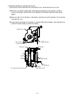
5 Remove the piping connections (4 positions) with the print head.
(Loosen the tube lock and pull out the tube.)
"Caution": Put wiping paper at the end of the tube to provide for an ink drip.
Circulation line
(Pipe signal: J)
Recovery line
(Pipe signal: A)
Supply line
(Pipe signal: E)
Makeup line
(Pipe signal: R)
Clamp
Fastening screws (4 locations)
【
The inside of a side cover
】
【RX2-S】
【RX2
-
B】
FG line
CN5
CN4
FG line
High pressure line
CN2
CN7
Summary of Contents for IJ RX2
Page 1: ...Service Manual HITACHI Printer Model RX2 Revision Feb 2014 Version A ...
Page 13: ...1 8 2 External views Rear side 1 2 2 Main body internal ...
Page 14: ...1 9 1 2 3 Print head ...
Page 101: ...3 26 Circuit diagram of EZJ127A ...
Page 102: ...3 27 Circuit diagram of EZJ127B ...
Page 116: ...3 41 Circuit diagram of EZJ129 ...
Page 164: ...4 40 5 Reset the time of the R air filter to 0 on the Parts usage time management screen ...
Page 247: ...7 Attached Drawing 7 1 Circulation System Diagram Circulation System Diagram 7 1 ...
Page 249: ...7 3 7 2 2 Electrical Connection Diagram RX2 B Basic model 7 3 ...


