


REV0 10.02.15
-H8-21-
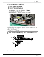
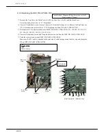
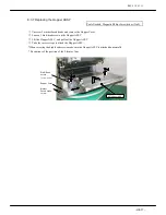
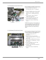
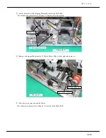
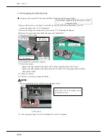
8.3.11 Replacing the Lamp Inverter (Front)
Tools Needed: Magnetic Philips Screwdriver (No.2)
#64 LAMP INVERTER
Bind head screw
Bind head screw
Connector(
J72
)
Connector(J71)
①
Remove the Main Cover (L) (R). For
instructions, please refer to “8.1 Preparation”
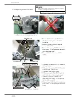
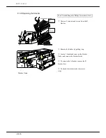
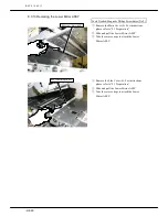
②
Unscrew 4 bind-head screws on the Eject Guide
and remove the Eject Guide. For instructions,
please refer to “8.3.5 Replacing the Scanner
ASSY”
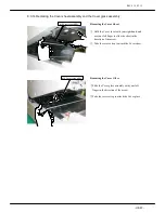
③
Please disconnect connector J72 and J71
attached to the Lamp Inverter
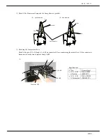
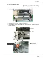
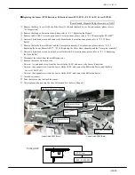
④
Unscrew 2 bind-head screws on the Lamp
Inverter and remove the Lamp Inverter.
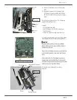
⑤
Take the reverse steps to attach the Lamp
Inverter
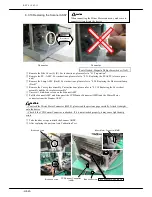
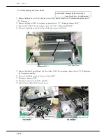
Caution:
Check cable route “8.3.4” and make sure
there is enough distance between the Motor Cable
and the Ultra Sonic Sensor Cable. Noise between
the 2 parts could cause errors in the Ultra Sonic
Sensor
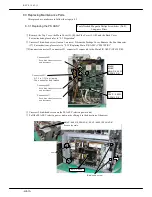
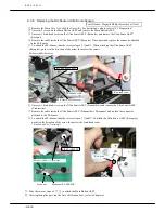
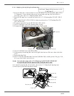
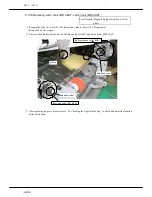
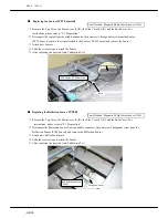
8.3.12 Replacing the Lamp Inverter ( Back)
Tools Needed: Magnetic Philips Screwdriver (No.2)
#64 LAMP INVERTER
Bind –head screw
Bind –head screw
Connector(J82)
Connector(J81)
①
Remove Side Cover (L) (R), and Back Cover.
For instructions, please refer to “8.1
Preparation”
②
Remove PS ASSY (electric power unit)
For instructions, please refer to “8.3.1 Replacing
the PS ASSY”
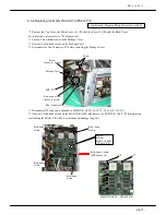
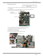
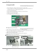
③
Remove Scanner ASSY (Back). For instructions,
please refer to “8.3.10 Replacing the Scanner
ASSY (Back)”.
④
Unscrew 2 bind-head screws on the Lamp
Inverter and the Lamp Inverter.
⑤
Disconnect connector J82 and J81 attached on
the Lamp Inverter.
⑥
Take the reverse steps to attach the Lamp
Inverter
Summary of Contents for HT-4139-28
Page 1: ...HT 4139 28 48 Scanner Maintenance Manual ...
Page 2: ......
Page 11: ... H2 5 2 5 Block Diagram ...
Page 22: ...REV0 10 02 15 H3 10 Lens Mirror Motor Mirror No 1 Mirror No 3 Mirror No 2 ...
Page 35: ...REV0 10 02 15 H7 2 ...
Page 63: ...REV0 2010 02 15 H7 30 ...
Page 89: ...REV0 10 02 15 H8 26 ...


